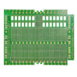
Edge Plating And Castellated Holes
A module that is soldered onto a mother board as if it were a component needs its connections on the edge or at the edge, so that the solder joint is accessible to the reflow process. Two techniques provide that: plating along the edge of the board itself, and holes that are drilled on the outline and cut in half so that their plating forms a solderable feature on the edge.
This article explains how the two are produced, the design rules that go with them, and the assembly consequences that a module designer has to accept.
What Edge Plating Is For
Edge plating puts copper on the cut edge of the board and connects it to a plane or a pad on one or both surfaces. It is used to make a ground connection to a chassis, to provide a controlled impedance transition into an edge connector, or to shield the edge of a radio frequency board.
The plating is applied after the outline is routed, which means the edge has to be prepared and activated before it is placed in the plating line. That additional step raises the cost and constrains the outline: an edge that is to be plated must be a clean, continuous profile without sharp internal corners, and the panel has to be handled so that the edge is exposed to the solution.

Castellated Holes In A Module
A castellated hole begins as a plated through hole placed on the outline of the module, and the outline routing cuts through the middle of the hole. What remains is a half cylinder of plated copper that opens onto the edge and is solderable from the side as well as from the top. The mother board has a matching pad, and the joint forms around the half hole during reflow.
The feature is what allows a module to be assembled with the same reflow process as the other components, without a connector and without a separate soldering step. The size of the half hole and the pitch between them are the two design variables, and both are constrained by the routing process and by the ability of the solder to form a fillet.
How The Edge Is Prepared
The outline is routed with a cutter of a defined diameter, and for a castellated feature the cut has to be positioned so that it passes through the centre of the hole within a tolerance. The depth of the cut and the wear of the cutter affect the result, and a cut that is offset produces a half hole that is asymmetric and therefore has a different solderability from its neighbours.
After routing the edge is deburred and cleaned. The debris from the laminate has to be removed completely, because a particle left on the half hole will prevent the solder from wetting and produce an open joint. For an edge that is also to be plated, the sequence is arranged so that the plating is applied after the routing and before the final surface finish.
Design Rules And Tolerances
The hole diameter for a castellated feature is limited by the routing cutter and by the remaining wall. A half hole that is too small leaves too little copper for the solder to grip, while one that is too large weakens the edge and may break during handling. The distance from the half hole to the internal circuitry has to allow for the routing tolerance, which is larger than the tolerance of an ordinary plated hole.
The pitch between the features is limited by the routing and by the solder process. A pitch that is tight relative to the solder volume produces bridges between adjacent half holes, and a pitch that is generous consumes board area. The designer should state the finished dimension of the feature rather than the drill size, because the routing and the plating both change it. The general outline considerations are described under board outline and mounting design and the plating process under electroplating additives.
Soldering A Castellated Module
The module is placed on the mother board with the half holes sitting over their pads, and the joint is formed during reflow. The solder has to wet the top of the half hole and the side, which means the fillet forms on two surfaces rather than one, and the paste volume has to be enough to reach both without bridging to the neighbouring feature.
The stencil aperture on the mother board is therefore larger than it would be for a flat pad of the same width, and the paste has to be positioned so that it covers the full length of the feature. A joint that is starved of solder wets the top and not the side, and the connection is mechanically weak even though it conducts. The solder volume is a design input rather than an outcome, and it should be specified with the assembly partner.
Inspection And Yield
Inspection of a castellated joint is visual from the side and from the top, and the acceptance criterion is a fillet that extends along the half hole on both surfaces. A joint that has wetted only one surface is the characteristic defect, and it is caused by too little paste or by contamination on the feature.
The yield of the module is driven by the condition of the edge. A burr or a smeared laminate on the half hole prevents wetting, and the defect is present before the module reaches the assembly line. Inspecting the modules on receipt, and confirming the dimensional tolerance of the features, is worth doing for a part that will be assembled at a high volume. The fabrication route is described in PCB design and fabrication.
Process Control and Verification
On a design of this kind, half hole is the item that decides how the rest of the board is arranged. Where the requirement is not written down, the shop supplies its own default, and the default is chosen for the process rather than for the design. The measurements that matter are the repeatable ones: conductor width and spacing, annular ring, finished hole size, plating thickness and surface finish are all verifiable on a coupon that travels with the panel.
Running a first article through the same checks as the production panel confirms that the two agree, and that comparison is the cheapest form of process control available at prototype stage.
FAQ
Can a castellated feature be added to an existing design? It can, but the outline and the hole positions have to be changed and the routing tolerance reviewed. It is a stack up and outline decision rather than a cosmetic one.
Why is edge plating more expensive than an ordinary board? Because the edge has to be prepared, activated and plated in a separate step after the outline is routed, and the panel has to be handled so that the edge is accessible to the solution.
What is the most common defect on a castellated joint? A joint that has wetted the top of the feature but not the side, which usually means too little paste or a contaminated edge. It conducts but is mechanically weak.