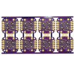
PCB Level Shielding: Board Shields, Cans and Faraday Cages
Enclosure shielding is the first line of defence against radiated emissions, and on modern products it is increasingly compromised. Ventilation openings, display windows, cable penetrations and connector cut-outs all break the shield, and the degradation is not gradual: a single large opening can take a well designed metal box down to the performance of an unshielded one. Pcb level shielding attacks the problem at the source instead.
Where Enclosure Shielding Runs Out
To work as intended, an enclosure has to be filtered wherever a cable crosses the shield boundary, which means a filter on every conductor entering or leaving the product. That requirement is often impractical for cost or mechanical reasons, and the shield is left partially effective. A board level shield removes the need for much of that filtering because the noise is contained before it reaches a cable.
Enclosure shielding also becomes less effective as frequency rises. Above a few gigahertz, the ratio between the size of the opening and the wavelength becomes large enough that the aperture behaves like a slot antenna. Suppressing the emission where it is generated follows the logic in EMI suppression design principles. Board level shielding keeps its attenuation in that region, because the geometry of the shielding structure scales with the component it covers rather than with the product.
Why the Board Is the Better Place
Attenuating interference between individual ICs is something a board shield can do and an enclosure cannot. As silicon geometries shrink and rise times shorten, noise margins fall, and a device that worked inside a noisy product five years ago may not work today. A local shield lets a noisy wireless module sit centimetres from a sensitive analog front end without the two interfering.
Cost and weight follow the same logic. A shield sized to cover one component costs a fraction of a fully shielded enclosure, and adding it does not force a mechanical redesign. The trade is that the shielding has to be designed into the layout from the beginning, because the ground plane under a shield cannot be added after fabrication.

What a Faraday Cage Actually Requires
A shield attenuates emissions only when it forms a complete six sided metal enclosure around the source. Five of those sides are made by the lid or can itself, and the sixth is the ground plane inside the board. The can has to be soldered or clamped to that plane continuously, not at a few isolated points.
Every real shield is compromised by its openings. Tuning holes, indicator windows, wire exits, construction seams and the gaps between individual ground connections to the can all leak. In an ideal box no emission would leave, so the practical engineering task is to keep the total aperture area, and the length of each individual slot, small relative to the wavelength of concern.
Fence and Lid Construction
The most common construction is two pieces: a fence that is soldered to the board around the component, and a lid that clips or welds onto the fence. That arrangement allows the component underneath to be inspected or reworked while the fence remains in place, which matters on a dense assembly where desoldering a shield risks damage to nearby parts.
The fence is usually attached by a through-hole solder tail or by a surface mount pad array. Through-hole tails give the strongest mechanical joint but must be soldered after the main assembly, which is slow and expensive. A surface mount fence is placed and reflowed with the rest of the components, which lowers cost but requires a pad pattern that can absorb placement tolerance.
Material Choice by Frequency
Tin-plated steel is the best general purpose choice for shielding below roughly 100 MHz, while tin-plated copper performs better above about 200 MHz. Tin plating is used on both because it ensures good solderability; without it, the joint to the ground plane becomes unreliable and the shield performs far below its rating.
Aluminium is generally not used for board level shields because it cannot be soldered to a ground plane in a normal reflow process. Brass, nickel silver, stainless steel and copper alloys all appear in commercial shield ranges. Where the product is used in hot and humid conditions, the material also has to resist galvanic corrosion and oxidation, and any regulatory requirement for restricted substances applies to the shield as it does to the rest of the assembly.
Ground Plane Integrity Under the Can
The ground plane under the shield must be solid, with no substantial slots or openings, because the plane is the sixth wall of the enclosure. Splitting the plane under a can turns it into a partially open box, and the leakage through the split rises quickly with frequency. Keep signal traces out of the region beneath the can unless they are essential to the shielded circuit.
Ground vias that stitch the can pads to the plane, and the plane to the rest of the ground system, have to be spaced closely enough that the gaps between them are electrically small. Where a via is omitted, the current has to detour and the resulting loop radiates. This is the same aperture leakage mechanism that limits enclosure shielding, applied at board scale.
Where to Place the Shield on the Board
Placement starts by identifying the noisy devices rather than the sensitive ones. A switching regulator, a crystal oscillator, a wireless module and a high speed memory bus all radiate, and each is a candidate for its own cavity. Grouping several of them under one shield with internal walls is usually cheaper than fitting separate cans, because the fence and the ground ring are shared between cavities.
<img src="https://www.gopcba.com/wp-content/uploads/2026/08/pcb9.jpg" alt="Tinned steel shield fence and lid fitted over the RF section of a board” />
The sensitive devices are then placed as far from the emitters as the layout allows, and the shield is sized to cover only what has to be covered. An oversized shield adds cost and height and makes rework harder, while an undersized one leaves the worst emitter outside the fence. The stackup decisions that support this placement are covered in EMI reduction through stackup and layout.
Assembly, Rework and Cost
Shields with removable lids, low profiles, multi-cavity patterns and ventilation openings are available as standard parts, and a single shield can cover several components while isolating them from each other with internal walls. Features such as connector cut-outs, I/O openings and RF absorber linings can be added when the standard part is not sufficient.
The electrical decision is usually straightforward; the manufacturing decision is not. A soldered shield cannot be removed without desoldering, so any part underneath becomes difficult to rework. Two piece designs with locking features that survive shock and vibration address this, but the locking feature adds height and cost, and the choice is normally driven by the expected repair rate.
Shield Cans and Thermal Management
A shield that traps heat under a lid can turn an emission fix into a reliability problem. Switching regulators and radio front ends dissipate real power, and closing a metal can over them raises the local ambient temperature. Perforating the lid helps, but each opening also leaks radio frequency energy, so the hole pattern has to balance airflow against attenuation.
Thermal vias under the shielded component conduct heat down to the ground plane, which acts as a heat spreader. Combining that path with a modest number of lid perforations usually keeps junction temperatures acceptable while preserving most of the shielding effectiveness.
Where the shield also provides mechanical protection, check that the lid does not contact tall components during vibration, and that the can is not used as a structural member. A shield should protect the circuit, not carry loads it was never designed for.
The nested shielding approach is worth restating, because it explains why a board level can is usually the first investment. Nested shielding places protection at the smallest practical volume, then adds another layer only where residual energy still escapes. Applying shields at the component and board level first keeps the size, weight and cost of the outer enclosure shielding to a minimum, and it avoids the situation where a large can is added to fix a coupling path that a smaller one would have closed.
FAQ
Can a shield can be added after the board is fabricated? Not fully. The can itself can be fitted, but the ground plane, the stitching vias and the pad pattern must be present in the original artwork. Adding a shield to an existing layout normally means a new revision.
Does a shield make decoupling unnecessary? No. The shield blocks radiated coupling, while decoupling addresses the supply impedance that generates the noise in the first place. A shielded board with poor decoupling still fails conducted emissions testing.
How large an opening is acceptable? As a rule, the longest dimension of any single opening should stay well below a quarter wavelength at the highest frequency of concern. At one gigahertz that is under seventy-five millimetres, and at five gigahertz it is under fifteen, which is why small products need tighter aperture control, as described in radiated EMI and regulator layout.