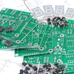
Microvia Laser Drilling In HDI Boards
A microvia is a small hole, typically under one hundred and fifty micrometres in diameter, that connects one layer to the next in a high density board. It is formed by a laser rather than by a drill, because a mechanical drill of that size cannot survive the rotational speed the diameter demands. The laser removes the dielectric layer by layer, and the shape of the hole it leaves sets the reliability of everything that follows.
This article covers the drilling step itself, the desmear that follows it, the aspect ratio limits that govern the stack, and how the hole is filled and checked.
What A Microvia Has To Achieve
The hole must land on the target pad with the full pad area exposed, must have walls that can be plated uniformly, and must be shallow enough that the plating chemistry can reach the bottom. Depth is therefore limited by the dielectric thickness rather than by the drill, and a typical laser-formed via is one dielectric layer deep, sixty to one hundred micrometres of material under a hole of similar diameter.
Because the hole is blind, it is opened from one side only. The energy must be enough to cut the resin and the glass reinforcement cleanly but not enough to damage the pad underneath, which acts as the stop layer. That window is narrow, and it is the reason the process is qualified against the actual laminate and copper foil used in production rather than against a sample from a supplier’s data sheet. Stack design is settled before drilling, and the options are set out under blind and buried via stack selection.
Choosing And Controlling The Laser
Two laser types dominate. An ultraviolet laser cuts by direct photochemical breakage of the polymer bonds, which produces a clean wall with little char and a small heat affected zone. A carbon dioxide laser cuts thermally and is faster, but it does not couple efficiently into copper, which is an advantage for stopping on the pad and a limitation for wall quality. Many shops run the two in sequence, using the ultraviolet source to open the resin and the carbon dioxide source to clear the remainder.
What matters in production is repeatability of the pulse energy, the beam position and the number of shots. Energy drift changes the hole diameter and the amount of copper removed from the pad surface; position drift moves the hole off the pad centre; too few shots leave resin at the bottom. The machine offsets are set from a coupon on each panel, so the pattern the laser follows is corrected for the actual dimensional movement of that panel. The overall artwork and drill data preparation for such a build is described under HDI CAM methods.

Desmear And Surface Preparation
Laser drilling leaves a residue of vaporised resin on the bottom of the hole and on the pad surface. If it is not removed, the plating adheres to the residue instead of to the copper, and the joint fails later under thermal cycling. Desmear removes it, usually with a permanganate treatment that swells and etches the resin, followed by neutralisation and a light etch of the copper to remove the oxide and the damaged layer.
The desmear must be strong enough to clean the bottom of the hole and gentle enough not to attack the resin around the rim of the via or to undercut the pad. Over-treatment shows up as a widened rim and a loss of dielectric thickness; under-treatment shows up as a dark bottom in a cross section and as voids between the plating and the pad. Both are process control problems, and both are judged on coupons rather than on the production panel.
Aspect Ratio And Stacking
The aspect ratio of a microvia, depth divided by diameter, sets how well the plating chemistry can throw copper into the hole. A shallow hole fills easily and a deep one tends toward a thin bottom and a thick rim. Accepted practice keeps a laser-formed via at a ratio below about one to one, and stacked vias, where one via sits directly on the copper of the via below, are limited further because each stack adds mechanical stress at the same location.
Where a deeper connection is needed, the design staggers the vias instead of stacking them, so each via lands on a pad offset from the one beneath. A staggered stack spreads the stress and keeps every via within the plating window. Stacking is used only where routing density demands it and where the qualification data supports it, and the number of stacked vias in one column is normally limited by the product specification.

Copper Filling And Planarity
A via that is left hollow and capped is acceptable for many designs, but a via in a pad that will carry a component ball must be filled and planarised, because a void under the ball becomes a void in the joint. Filling is done by plating, by conductive paste, or by a combination in which plating closes the mouth and paste fills the body. Whichever route is used, the result has to survive thermal cycling without the fill pulling away from the wall.
Planarity is the second requirement. The copper over the filled via must be flat enough that the solder paste deposits evenly on the pad, and any dimple or bump changes the volume of paste in that deposit. The fill chemistry and the plating parameters that control it are treated in more detail under electroplating and via filling for HDI, and the defect signatures that appear when the parameters drift are collected under copper plating defects prevention.
Inspection And Reliability
A microvia cannot be inspected by looking at it. The usual checks are a cross section of a coupon that was drilled and plated with the panel, a resistance measurement of a daisy chain that runs through many vias, and a thermal cycling test that stresses the chain until the resistance rises. The resistance chain is valuable because a single marginal via does not change the reading much, so the test is repeated in large numbers and the distribution is watched rather than the individual value.
Reliability of a microvia is dominated by the interface at the bottom of the hole. If the target pad was over-etched before lamination, or if the desmear left residue, the interface becomes the crack initiation site under thermal cycling. Failures usually appear as a crack that runs around the base of the barrel and separates it from the pad, and in a cross section the crack is easy to see once it is there but almost impossible to predict from the surface of the board.
Additional Considerations for This Build
Practical attention to microvia laser drilling pays for itself here, because it decides whether the finished board behaves as the drawing intended. Where the requirement is not stated on the fabrication drawing or in the assembly notes, the shop has to assume a default, and that default is rarely the value the design was simulated with. Stating microvia laser drilling explicitly, together with the tolerance that applies, removes the assumption and keeps the result predictable from batch to batch.
FAQ
Can a microvia be drilled through more than one dielectric layer? It can be, but the depth limit is set by the plating window rather than by the laser, and a ratio above roughly one to one makes a reliable bottom plating difficult. Deeper connections are normally made by stacking or staggering several single-layer vias.
Why is the target pad sometimes damaged? Laser energy that is too high, or too many shots after the dielectric has already been opened, removes copper from the pad and makes it thin. The fixed offsets from a per-panel coupon are the usual remedy.
Is a hollow microvia acceptable? For a via that simply carries a signal and is not under a component pad, yes. For any via inside a land pattern that will take a solder ball, the via must be filled and planarised so that the joint is not disturbed.