Surface Insulation Resistance Test On Assemblies
Surface insulation resistance is a measure of how well a surface resists the flow of leakage current between two conductors. On an assembled board it is affected by the flux residue left behind, by the cleanliness of the process and by the humidity of the environment in which the board will operate.
The test is one of the few that evaluates the combination of materials and process rather than a single item. It is used to qualify a flux, to verify a cleaning process and to confirm that a change on the line has not made the residue more conductive than it was.
What The Test Measures
A pattern of interleaved conductors is printed on a test board and a voltage is applied between the two halves. The current that flows is measured and converted into a resistance, which is normally reported in ohms or in ohms per square of the pattern.
Values above 10 to the 8 ohms are generally considered acceptable for a clean no-clean process, while values below 10 to the 6 ohms indicate a real risk of leakage and electrochemical migration. The absolute number matters less than the trend and the comparison with a known good reference.
Test Coupon And Pattern Design
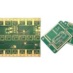
The test coupon should reproduce the production surface, which means the same solder mask, the same surface finish and the same assembly process as the real board. A coupon that is only cleaned and not assembled does not test the flux residue that the process actually leaves behind.
The conductor pattern is defined by an industry standard, with a typical line width and spacing of 0.4 to 0.5 mm. The pattern should be representative of the tightest spacing on the product, because leakage current increases sharply as the gap narrows. The way a fine pattern is laid out is described under PCB pad design standards.
Bias Voltage And Humidity Conditions
Bias voltage provides the driving force for the electrochemical processes that degrade the surface. It is normally applied continuously during the test, at a level of 10 to 50 volts DC, and the measurement is taken with the bias removed so that the reading reflects the surface rather than the applied field.
Humidity is the other essential variable. The standard condition is 85 C and 85 percent relative humidity, though a lower temperature with a high humidity is also used for products that will never run hot. Condensation on the coupon should be avoided, since it produces a reading that reflects a water film rather than the surface chemistry.
Flux Residue And Cleanliness
Flux residue is the single most common cause of a failed result. A no-clean flux is designed to leave a benign residue, but that design assumes the correct reflow profile and the correct amount of flux. An under-heated joint leaves the residue active and it absorbs moisture from the air.
Cleaning removes the residue but introduces risks of its own. An incomplete rinse can leave ionic material from the cleaning chemistry, and that is more conductive than the flux it replaced. The cleaning process should be validated with the same test rather than assumed to be beneficial. The materials involved are described under conformal coating and board protection.
Reading And Interpreting Results
Results are usually collected over a period of days or weeks, because the surface takes time to reach equilibrium with the chamber. A reading taken after a few hours is a screening value, while the value after 168 hours is the one normally quoted for qualification.
The recovery after the bias is removed is also informative. A surface that recovers quickly is behaving as a clean insulator, while one that stays conductive suggests that ions have migrated into the material and cannot simply be driven back out again.
Common Problems And Fixes
The usual causes of a low reading are an incomplete cure of the solder mask, flux trapped under a component, and contamination from handling. Each of them can be isolated by testing a coupon that has been processed with only one of the suspect steps included.
Electrochemical migration is the failure mode that follows a low reading. Dendrites grow between the conductors and eventually cause a short, and once they form the assembly must be replaced. How the result is used as an acceptance criterion is described under PCB design quality characteristics.
Process Control and Verification
On a design of this kind, humidity is the item that decides how the rest of the board is arranged. Documenting the assumption is part of the design work, and a short note on the drawing prevents a question that would otherwise arrive a day later and cost a day of schedule. The process window is set by the narrowest step in the flow, so an improvement anywhere else shows up as margin rather than as yield until that step is addressed.
A short note on the drawing about handling, storage or packaging is often worth more than an extra decimal place on a tolerance. Where a value sits close to a process limit, the drawing should say so, since the shop can then open the process window rather than working to a nominal figure that carries no tolerance.
A stack-up that is drawn rather than described removes most of the ambiguity from a quotation, and it lets the fabricator price the board against the dielectric and copper weights that will actually be used. Where the requirement is not written down, the shop supplies its own default, and the default is chosen for the process rather than for the design.
Process Control and Verification
On a design of this kind, humidity is the item that decides how the rest of the board is arranged. Documenting the assumption is part of the design work, and a short note on the drawing prevents a question that would otherwise arrive a day later and cost a day of schedule. The process window is set by the narrowest step in the flow, so an improvement anywhere else shows up as margin rather than as yield until that step is addressed.
A short note on the drawing about handling, storage or packaging is often worth more than an extra decimal place on a tolerance.
Process Control and Verification
On a design of this kind, humidity is the item that decides how the rest of the board is arranged. Documenting the assumption is part of the design work, and a short note on the drawing prevents a question that would otherwise arrive a day later and cost a day of schedule. The process window is set by the narrowest step in the flow, so an improvement anywhere else shows up as margin rather than as yield until that step is addressed.
A first article check confirms that the process and the drawing agree on the points listed above, and that the coupon data supports the values used in the design.

Where a measurement falls outside the expected window, the sample is retained so that the cause can be established before the balance of the batch is released.
FAQ
Does a no-clean process still need this test? Yes. The test is exactly how a no-clean process is qualified, because the residue is permanent and its behaviour has to be demonstrated rather than assumed.
How long should the test run? Many specifications use 168 hours of biased exposure with intermediate readings. Longer runs are used where the environment is aggressive or where the residue chemistry is new.
Can the test be done on a production board? It is usually done on a coupon, but a production board can be used where the pattern exists. The coupon is cheaper and gives a consistent geometry for comparison.