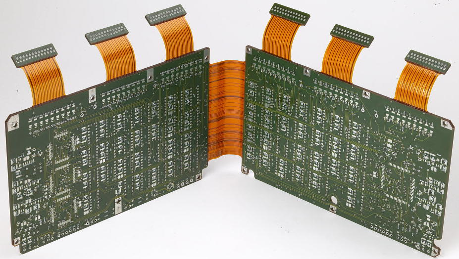
Thermal Cycling and Reliability Testing
What Thermal Cycling Tests
Thermal cycling takes an assembly through repeated temperature extremes and looks for the failures that the expansion and contraction cause. Because the board, the solder and the components expand at different rates, every cycle strains the joints, the plated barrels and the laminate, and the strain accumulates until a crack forms. The test is therefore a way to compress years of service into weeks, and its value depends on whether the conditions and the failure mode resemble the intended use. A test that is run at conditions the product will never see proves very little about it.
The Standard Conditions
The standard tests are defined by their temperature range, the dwell at each extreme, the ramp rate and the number of cycles. A common profile cycles between minus 40 and plus 125 degrees Celsius with a defined dwell, and the number of cycles is chosen to represent the product’s life. The dwell matters because the damage occurs once the assembly has reached the extreme and the differential expansion is fully developed; a test with a short dwell may complete the same number of cycles in less time and find fewer failures. The ramp rate matters as well, since a fast ramp adds a rate dependent component that a real product may not experience.
The Failures It Reveals
The characteristic failure is solder joint fatigue. A crack initiates at the edge of a joint where the strain is concentrated, propagates through the bulk or along the interface, and eventually opens the connection. The crack is often not detectable electrically until it is nearly complete, which is why the monitoring during the test should be continuous rather than at the end. Other failures include plated barrel cracks in the vias, delamination at a laminate interface, a crack in a component’s termination or body, and a failure of an adhesive or a coating. Which one appears first depends on the design and on the weakest link in the chain.

Monitoring During the Test
A thermal cycling test is only useful if the failure is detected when it occurs. The usual method is to connect the assembly’s daisy chained nets to an event detector that continuously monitors the resistance and records the cycle at which a discontinuity appears. Without the event detector, a test can complete with several broken nets and no record of when they broke, which loses the data that the test was run to obtain. Inspecting the assembly between cycles, or after the test only, means the failure is found but its origin is not, and the number of cycles to failure is the number that matters for the reliability prediction.
Analysis of the Failure
When a failure occurs, the analysis is as important as the test. A microsection through the failed joint shows whether the crack is at the interface, in the bulk or in the intermetallic layer, and the path of the crack indicates the mechanism. Comparing a failed joint with an untested one and with a joint from a different design or process shows what changed. The location of the failures across the assembly is also informative: a failure concentrated at the corners of a package points to the thermal expansion mismatch, while one at a specific location on the board suggests a local effect such as a heavy copper plane. The analysis turns a number into a reason.
Using the Result
A thermal cycling result should be used to make a decision, not just to fill a report. Where the failures are acceptable in number and position, the test supports the design; where they are not, the analysis points to the change, which may be a different solder alloy, a different surface finish, an underfill, a change in the pad geometry or a change in the material. Where the result is marginal, a longer test or a more severe condition may be justified, but the conditions should be linked to the service environment rather than chosen for severity. The output of the test should be a design decision with a reason.
Limits of the Test
Thermal cycling does not reproduce every field failure. It does not account for vibration, for humidity, for contamination or for the combination of stresses that a real product sees, and it applies a uniform condition to a sample rather than the distribution that a population experiences. Its acceleration factor depends on assumptions about the failure mechanism, and if the mechanism in the test is not the mechanism in the field, the prediction is wrong. The result is therefore best treated as a comparison between designs and processes rather than as an absolute life prediction, and it should be combined with the other tests and the field data.
Combined Stress and Qualification Programmes
Real products rarely see one stress at a time, and a qualification programme that tests them separately can miss the interaction. A common approach is a combined test that applies temperature cycling together with vibration and humidity, which is closer to a service environment and often reveals a failure that the individual tests did not. The programme should be built from the product’s actual environment rather than from a generic standard, and the conditions should be recorded with their justification. Where a customer specifies a standard, the standard defines the conditions and the sequence, and the programme should follow it rather than an equivalent that seems more reasonable.

FAQ
What does thermal cycling reveal? Failures that accumulate from expansion mismatch: solder joint fatigue, barrel cracks, delamination and component cracks.
Why does the dwell matter? The damage develops once the assembly reaches the extreme; a short dwell completes the cycle without applying the full strain.
How are failures detected? By continuously monitoring daisy chained nets with an event detector that records the cycle of the discontinuity.
What does a microsection add? The crack path and the mechanism, which point to the design or process change that will fix it.
Can the result predict field life? Only with assumptions about the mechanism; it is more reliable as a comparison between designs.
Conclusion
Thermal cycling compresses years of expansion mismatch into weeks, and its value lies in the failures it reveals and the decisions it supports. Monitor continuously and analyse the failures. Reliability testing belongs to PCBA testing, the joints under test come from SMT PCB assembly, and the acceptance criteria are part of quality management. Reliability planning for a new product begins during prototype PCB assembly in 2026.