PCB Visual Inspection: A Practical Checklist
Two boards can both pass electrical test and still be very different products. One will run through assembly without incident and survive a decade in the field; the other will produce solder defects, a failed connector insertion or a field return six months later. PCB visual inspection is the step that separates them, and it works best when the acceptance criteria are written down before the boards are ordered rather than argued about after delivery.
What the Inspection Is For
Inspection is not a search for beauty. It is a check that the physical board matches the design intent in the ways that matter to the next process: paste printing, placement, reflow, connector insertion and mechanical assembly. A pad that is slightly small, a solder mask opening that is slightly misplaced or a surface finish that is uneven may pass a visual glance and still cause a defect downstream.
It also protects both parties. When a fabricator and a customer disagree about whether a scratch is acceptable, the argument is really about a missing specification. A written checklist, referenced to a workmanship standard and amplified by the customer drawing, removes most of that ambiguity before it becomes a commercial dispute.
Surface, Copper and Trace Integrity
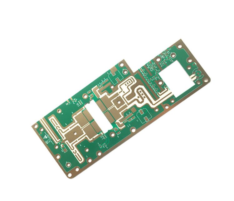
The survey begins with the panel as a whole: cleanliness, staining, fingerprints, evidence of handling, and any discolouration that suggests contamination or excessive heat. Copper features come next. The inspection looks for opens and shorts, for traces that are thinner than designed, for nicks and pinholes in a conductor, for etch residues between fine lines and for the over etching that leaves a conductor narrower than the tolerance allows.
On fine line and high density work these checks matter most, because the margin between a good trace and a marginal one is small. It is worth remembering that visual inspection cannot confirm impedance or the electrical properties of a fine trace; those are verified by measurement and by test coupons rather than by eye.

Pads, Solder Mask and Legend
Pads are checked for size, shape, position, cleanliness and damage, and the solder mask is checked for registration. A mask that encroaches on a pad reduces the area available for the joint, and on a fine pitch device even a small encroachment changes the amount of paste that releases. Mask that has been scratched, blistered, cracked or contaminated is a defect because it no longer protects the copper beneath it.
The legend is a functional marking, not decoration. Reference designators, polarity marks, pin one indicators and warning text have to be legible, complete and in the right place, and they must not print over a pad that will be soldered. Where a barcode or a data matrix is used for traceability, its contrast and the quiet zone around it have to be adequate for the reader the customer will use.
Holes and Surface Finish
Holes are examined for missing and mispositioned drillings, for blockage, burrs, rough edges, drill smear and contamination, and for obvious plating defects visible in the barrel. What the eye cannot see is more important here than what it can: hole diameter, position and copper thickness in the barrel are verified by measurement and by microsection rather than by looking into the hole.
Surface finish is judged by uniformity, colour, oxidation, roughness and coverage, with the acceptance criteria depending on the process. An immersion gold, an organic preservative and a hot air levelled tin each have their own normal appearance, and comparing one against the other leads to false rejects. The behaviour of one of the common finishes is described in OSP as a solderability preservative.
Edges, Warpage and Delamination
The board edge carries the results of routing, scoring and punching, so it gets specific attention: burrs and sharp edges that could injure an operator or damage a connector, chipped laminate, delamination at the edge, and the dimensions and chamfers of any edge that mates with a connector or a card guide.

Warpage is measured with a tool rather than judged by eye, because it is a dimensional property and the acceptance limit is defined in the workmanship standard. Delamination and blistering inside the board are harder to detect visually; a suspicious area is normally confirmed by microsection. Both defects become more likely on large, thin, high layer count boards and on assemblies that will be soldered with a lead free profile.
Contamination and Cleanliness
Flux residue, oil, dust, fingerprints, chemical residues and metal particles all sit in the same category, and their severity depends on where they land. Contamination on a pad affects solderability; contamination between fine traces can create leakage; residue on a high impedance node can change the behaviour of an analogue circuit. For automotive, medical and industrial products the visual check is usually supplemented by ionic contamination testing.
Cleanliness is also a process indicator. Boards that arrive with fingerprints suggest that handling controls are weak, and the same weakness will show up in other ways. Recording the finding, rather than simply cleaning the board, is what makes the inspection useful. Residue limits and the tests used to confirm them are closely related to the choice of surface finish, which is discussed in conformal coating for board protection where a coating is applied after assembly.
Where AOI Inspection Fits
Automated optical inspection compares the board against reference data and is fast, repeatable and able to check every unit. It is well suited to confirming that features are present, that the pattern matches the artwork and that no gross defect exists. It is less well suited to judging cosmetic conditions and to defects that depend on depth, such as a shallow scratch or a partly filled hole.
In practice the two methods are complementary. AOI inspection performs the systematic comparison and flags locations, and human inspection judges the flagged areas and the conditions that the machine cannot classify. The split should be defined in the procedure so that neither method is asked to do work it cannot do. The same division of labour applies to assembly, where automated optical inspection after reflow checks placement and visible joints while the hidden joints require another method entirely.
Writing an Acceptance Standard
A usable checklist states the criterion, the method and the limit for each item. The criterion describes what is being checked, the method says whether it is judged by eye, by magnification or by measurement, and the limit gives the number that decides acceptance. Items that the customer cares about are added to the drawing so that they appear on the shop floor rather than only in a document.
The standard also has to allow for the class of product. A consumer board and a high reliability board can share a checklist but not the same limits, and the difference should be explicit. The characteristics that distinguish a well made board from a merely acceptable one are discussed in PCB design quality characteristics.
FAQ
Does every board need 100 percent inspection? Not necessarily. Appearance criteria are often checked by sampling for standard products, while high reliability and safety related products are inspected in full.
Can a visual defect be accepted anyway? Yes, if the workmanship standard and the customer drawing allow it. A scratch outside the functional area is normally acceptable where one across a pad is not.
Is AOI a replacement for manual inspection? No. It is faster and more consistent for pattern comparison, but it cannot judge every cosmetic condition or measure the properties that need a tool.