If you want to understand PCBA Processing Cost, it is important to break down the entire PCB Assembly process and identify the major cost drivers involved in production.
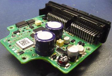
PCBA, or Printed Circuit Board Assembly, refers to a completed PCB populated with electronic components. The overall process generally includes the bare PCB, electronic components, SMT Assembly, DIP Assembly, soldering, inspection, and electrical testing.
The prices of bare PCBs and electronic components are generally relatively transparent and can be compared among suppliers. Therefore, differences in PCBA quotations often come from the assembly process, production efficiency, labor requirements, testing requirements, and quality control.
For manufacturers and customers, understanding these cost factors is essential for obtaining an accurate quotation and controlling overall manufacturing costs.
Key Factors Affecting PCBA Processing Cost
The cost of PCBA production can vary significantly depending on the product design, component types, production volume, assembly method, testing requirements, and quality standards.
The following four areas are among the most important cost factors.
1. Auxiliary Materials
Auxiliary materials are essential to the assembly process. Common materials include solder paste, solder wire, flux, adhesives, cleaning agents, and fixtures used during production and inspection.
Among them, solder paste plays an important role in SMT Assembly. Its cost depends on alloy composition, particle size, flux formulation, storage requirements, and application requirements. Higher-performance solder pastes may provide better printing consistency, wetting performance, and solder-joint reliability, but they may also increase production costs.
Other consumables can include:
- Solder wire for manual soldering and rework
- Flux for improving solder wetting
- UV-curable adhesives for specific component-fixing applications
- Reflow and assembly fixtures
- Cleaning chemicals
- Stencils and other production consumables
However, material price alone should not determine the purchasing decision. A low-cost material that causes printing problems, soldering defects, or frequent rework may ultimately increase the total PCBA Processing Cost.
2. SMT Assembly
SMT Assembly is one of the major cost components in modern PCB production.
The cost of SMT placement is affected by several factors, including the number of components, placement points, component packages, component size, production volume, feeder requirements, and machine setup time.
For example, a PCB containing a large number of small passive components may require significantly more placement operations than a board with only a few large components.
Common factors affecting SMT costs include:
- Total component count
- Number of placement points
- Component package types
- Fine-pitch and micro-pitch components
- BGA and QFN packages
- Component availability and handling requirements
- Feeder setup and changeover time
- Production volume
- Stencil and solder paste requirements
- AOI and other inspection requirements
In general, higher production volumes can reduce the average processing cost per board because machine setup and programming costs can be distributed across more units.
At the same time, component complexity should not be evaluated only by package size. Fine-pitch components, BGAs, QFNs, and other high-density packages can require more demanding process control and inspection.
3. DIP Assembly and Through-Hole Soldering
DIP Assembly, also known as through-hole assembly, is another important part of PCBA production.
Unlike fully automated SMT placement, some through-hole components may require additional preparation, forming, insertion, soldering, trimming, and inspection. Depending on the product design, these operations may involve significant manual labor.
Typical through-hole processes include:
- Component preparation and lead forming
- Manual or automated component insertion
- Component alignment and inspection
- Wave or selective soldering
- Lead trimming
- Visual inspection
- Manual touch-up or rework when necessary
The cost of DIP Assembly depends heavily on component quantity, component geometry, insertion method, soldering technology, production volume, and labor requirements.
For products containing many irregularly shaped through-hole components, manual operations can become a significant portion of the total assembly cost.
However, it is not accurate to assume that DIP assembly is always the most expensive part of PCBA production. The actual cost structure depends on the specific product and production requirements.
4. PCB Testing and Inspection
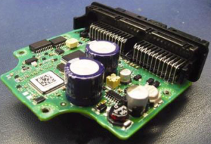
Testing is another important factor in PCBA Processing Cost.
Different products require different levels of inspection and testing. A simple PCB may only require visual inspection and basic electrical testing, while complex communication, industrial, medical, or automotive electronics may require multiple testing stages.
Common testing methods include:
- Automated Optical Inspection (AOI)
- X-ray inspection
- In-Circuit Testing (ICT)
- Flying probe testing
- Functional testing (FCT)
- Programming and firmware verification
- Power-on testing
- Signal and communication testing
Testing fixtures can also affect the total cost. Simple fixtures may be relatively inexpensive, while customized ICT or functional test fixtures can require considerably more engineering work and equipment investment.
Testing time should also be considered. If every PCBA requires a long functional test cycle, the additional equipment occupancy and labor time can affect the final quotation.
Therefore, customers should define test requirements clearly during the quotation stage.
How to Reduce SMT Soldering Defects
Reliable SMT Soldering is critical to PCBA quality. Poor soldering can result in open circuits, solder bridges, insufficient solder joints, component displacement, voids, and other defects.
In severe cases, defective solder joints may cause electrical failures or reduce the long-term reliability of the product.
For this reason, manufacturers should establish appropriate process controls throughout solder paste printing, component placement, reflow soldering, inspection, and rework.
1. Control Solder Paste Printing
Solder paste printing is one of the most important steps in SMT Assembly.
Insufficient solder paste can result in weak solder joints, while excessive solder paste can increase the risk of solder bridging.
Important control factors include:
- Stencil thickness
- Aperture design
- Printing pressure
- Printing speed
- Squeegee condition
- Solder paste viscosity
- Storage and handling conditions
- PCB and stencil cleanliness
Proper stencil design is especially important for fine-pitch components and high-density PCB layouts.
2. Optimize the Reflow Soldering Profile
For automated SMT production, reflow soldering is normally used rather than manual soldering irons.
The reflow profile should be matched to the solder paste and component requirements. Key parameters include preheating, soaking, peak temperature, and cooling rate.
An unsuitable profile may cause:
- Insufficient soldering
- Poor wetting
- Component damage
- Excessive voiding
- Solder bridging
- Thermal stress
- PCB warpage
Therefore, the reflow profile should be verified and controlled during production.
3. Use the Correct Soldering Tools for Manual Rework
Manual soldering is generally used for rework, repair, prototypes, or specific through-hole operations rather than standard automated SMT placement.
During manual soldering, the soldering iron tip should be selected according to the component size, pad geometry, and thermal requirements.
A tip that is too small may transfer insufficient heat, increasing soldering time and potentially causing cold solder joints. A tip that is too large can transfer excessive heat and damage components or PCB pads.
The correct tip geometry helps achieve efficient heat transfer while minimizing thermal stress.
4. Apply Appropriate Soldering Temperature
Temperature control is critical during manual soldering and rework.
Excessive temperature can damage components, solder mask, PCB pads, or internal structures. Insufficient temperature can result in poor wetting and unreliable solder joints.
The appropriate temperature should be determined based on the solder alloy, component specifications, PCB thermal characteristics, and process requirements.
5. Control Flux Usage
Flux improves solder wetting and helps remove surface oxides during soldering. However, excessive or inappropriate flux application can create residue and may affect long-term reliability if the flux chemistry is not properly controlled.
For this reason, manufacturers should select flux according to the soldering process and follow the material supplier’s application requirements.
If required, appropriate PCB cleaning should be performed after soldering.
Proper Manual Soldering and Rework Practices
When manual soldering or rework is necessary, operators should avoid excessive mechanical force.
Applying too much force to a component lead or PCB pad can cause:
- Pad lifting
- Copper trace damage
- Delamination
- Component displacement
- Solder-joint damage
The soldering iron should provide sufficient heat to melt the solder efficiently without excessive physical pressure.
During rework, the operator should also avoid repeatedly heating the same pad or component. Excessive rework cycles can increase thermal and mechanical stress and potentially reduce PCB reliability.
Avoid Unnecessary Rework
Rework should be controlled according to documented procedures rather than performed repeatedly simply to achieve a visually perfect appearance.
Repeated heating and mechanical manipulation can damage copper pads, solder joints, component leads, and PCB laminates.
A professional PCB Assembly process should therefore define clear acceptance criteria based on applicable IPC requirements, customer specifications, and product reliability requirements.
When a soldering defect is identified, the preferred approach is to:
- Identify the root cause.
- Determine whether rework is permitted.
- Use an approved rework procedure.
- Control the number of thermal cycles.
- Inspect the repaired area.
- Perform electrical testing when required.
- Record the defect and corrective action.
This approach helps prevent the same problem from recurring in mass production.
How Kingda Controls PCBA Manufacturing Quality
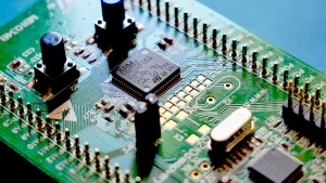
For reliable PCBA Manufacturing, cost control should never be separated from process control.
Kingda can manage PCB assembly requirements through coordinated control of material selection, SMT placement, through-hole assembly, soldering, inspection, testing, and production traceability.
A comprehensive quality system can include:
- Incoming material inspection
- Solder paste and material control
- SMT process monitoring
- AOI inspection
- X-ray inspection when required
- Through-hole soldering inspection
- Functional and electrical testing
- Rework process control
- Production traceability
- Final quality inspection
By controlling these processes systematically, manufacturers can reduce defects, minimize unnecessary rework, improve production efficiency, and achieve a more predictable PCBA Processing Cost.
Conclusion
The total PCBA Processing Cost is determined by much more than the price of the bare PCB and electronic components. SMT Assembly, DIP Assembly, auxiliary materials, testing, labor, equipment utilization, production volume, and quality requirements all contribute to the final cost.
At the same time, cost reduction should not come at the expense of PCB reliability. Optimized solder paste printing, controlled reflow profiles, appropriate manual rework, effective inspection, and comprehensive testing are essential for consistent PCB Assembly quality.
By evaluating both manufacturing cost and process capability, customers can select an appropriate PCBA manufacturing partner and achieve a better balance between cost, quality, production efficiency, and long-term product reliability.