Projector Mainboard: Key Checks Before Release
A compact projector fits a display engine, a battery and a processor into a space the size of a book. Projector mainboard design is dominated by the light source, because the led driver and its power loop set the size, the heat and the interference on the board.
What the Projector Mainboard Does
The board drives the optical engine, decodes video from its inputs, manages the battery and controls the fan and the audio. It also provides the user interface and the wireless connection.
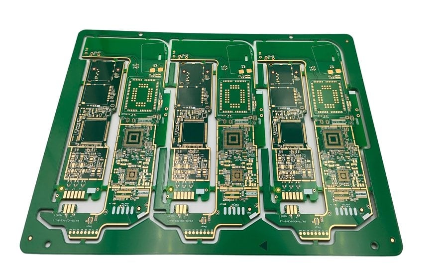
Its shape is defined by the optical path rather than by the electronics. The engine, the lens and the battery occupy most of the volume, so the board is usually built around them in an L or a U shape.
The Processor Platform
The processor decodes the video, drives the display device inside the optical engine and runs the operating system. It is usually a media device with an integrated display controller and hardware decoding.
A typical platform of this class is built on a six to eight layer board, about one and a half millimetres thick, with a thin dielectric to the first plane. The memory bus is routed as a matched group, and the layout follows the vendor reference design closely.
Optical Engine Interface
The engine contains the display device, the illumination optics and the projection lens. Its electrical interface carries the display data, the timing signals and the power for the illumination.
The connector is a mechanical interface as well, because the engine has to be aligned optically. Its position on the board is fixed by the mechanical design, and the routing to it is planned before the rest of the layout.
LED Driver and Light Source
The light source is driven by a current regulated supply that switches at a high frequency. Its inductor, its switch node and its sense resistor form the highest current loop on the board.
That loop is kept as small as the layout allows, because its area sets both the radiated field and the voltage spike at the switch. The led driver is also the largest heat source after the processor.
The Power Loop
The supply chain runs from the adapter or the battery to the system rail, then to the driver and to the processor. Each conversion adds loss, so the number of stages is kept to a minimum.
The battery charging path and the system path share the same connector, and the loop between them has to be laid out so that the charge current and the load current do not interfere. Our notes on converter layout describe the same measures.
Battery and Charging
A portable projector runs from a battery or from the adapter, and it may charge while it is running. That combination is the hardest case for the charger, because the load and the charge current add.
The charge current has to fall as the cell voltage rises, and the board has to remove the heat that the charging and the load together produce. Thermal limiting in the charger is a normal part of the design.
Heat Management
Three sources produce heat in a small volume: the processor, the led driver and the light source itself. The optical engine usually has its own thermal path to the housing.
The board contributes copper area, thermal vias and a defined contact with the metalwork. The fan moves air across the remaining surfaces, and its intake and exhaust paths are part of the mechanical design.
Shielding and Interference
The switching driver, the memory bus and the display link all radiate. Where the radio module and the light source share the same small enclosure, shielding becomes a design requirement rather than an option.
A shield over the driver reduces the field that reaches the wireless module, and a shield over the module protects the receiver. The shield is bonded to ground at many points so that it does not become an antenna itself.
Memory and Storage
The processor needs memory for the operating system and the video buffers, and storage for applications and media. Both are usually soldered to the board to save space.
The memory is routed to the vendor reference, and the storage interface is kept short. Where a card socket is provided, its position follows from how the user reaches it.
Video Inputs and Wireless
Inputs include high definition multimedia, USB and often a wireless display link. Each connector is placed on an edge that the enclosure exposes, and each has its own protection.
The wireless module needs an antenna arrangement that works inside a metal or metallised housing. Placing the antenna at the edge of the board, away from the light source, is the usual solution.
Audio and Fan Control
A small speaker and a fan are the two mechanical loads the board drives. Both are inductive, and both are switched, so their drivers need suppression and their return currents need a defined path.
Fan speed is controlled from a temperature measurement and reported to the software. The fan is the only moving part, and its life is the first limit on the life of the product.
Stackup and Layer Count
The board carries a high speed memory bus, a display link, a switching driver and several analogue nodes. A six to eight layer stackup with a thin dielectric to the first plane is typical.
The stackup has to be symmetrical to stay flat, and the plane structure is planned so that the driver loop and the memory bus do not share a return path. The rules are described in our notes on layer stackup.
Bring Up and Optical Alignment
Bring up follows the usual order: rails, clock, debug port, memory, storage and finally the display and the light source. The optical engine is brought up last, because it draws the most current.
Alignment is a mechanical operation carried out after the electronics work. The board has to allow the engine to be adjusted and then fixed, which is why the mounting features are part of the layout.
Testing and Validation
Validation covers the picture quality, the light output, the battery run time, the charging behaviour and the temperature of the light source. Each of them is measured on a complete unit rather than on a board.
The thermal test is run at the highest brightness and the highest ambient, because that is the state in which the product is most likely to throttle. The same review criteria described in our design quality notes apply here.
Mechanical Integration of the Board
The board is shaped around the optical path and the battery, so its outline is irregular and its mounting points are few. Stiffness comes from the enclosure rather than from the board itself.
Connector positions are fixed by the openings in the case, which means the mechanical design and the layout proceed together. The rules used for those interfaces are the same as any board outline decision.
FAQ
Why is the LED driver loop so important? Because it carries the largest switched current on the board. Its area determines the radiated field, the switching spike and the heat, which is why it is laid out before anything else.
Can the projector run and charge at the same time? It can, if the charger and the thermal design allow the combined current. Where they cannot, the firmware reduces the brightness while charging.
Does the board need a shield? Usually over the driver, and sometimes over the wireless module. The need is confirmed by measuring the radio performance with the light source running.