RF PCB Material Types: The Complete Engineer’s Guide to High-Frequency Laminates
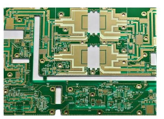
RF PCB material types fall into four major families: hydrocarbon-ceramic (Rogers RO4000 series), ceramic-filled PTFE (Rogers RO3000 series, Taconic TLY), pure PTFE (RT/duroid), and thermoset high-speed laminates (Isola Astra MT77, Panasonic Megtron). The right choice depends on your operating frequency, loss budget, and fabrication constraints—below 20 GHz, RO4350B offers the best balance; above 20 GHz, PTFE-based materials are mandatory.
Why RF PCB Material Selection Matters
At frequencies above 1 GHz—and especially in the 24–77 GHz mmWave bands driving 5G, automotive radar, and satellite communications—the PCB substrate’s dielectric properties directly determine signal loss, impedance accuracy, and overall system performance. Standard FR-4 becomes impractical above ~3 GHz due to its high dissipation factor (Df ≈ 0.020) and inconsistent dielectric constant (Dk varies with frequency, temperature, and moisture). RF PCB materials are engineered to solve these problems through specialized ceramic, PTFE, and hydrocarbon formulations.
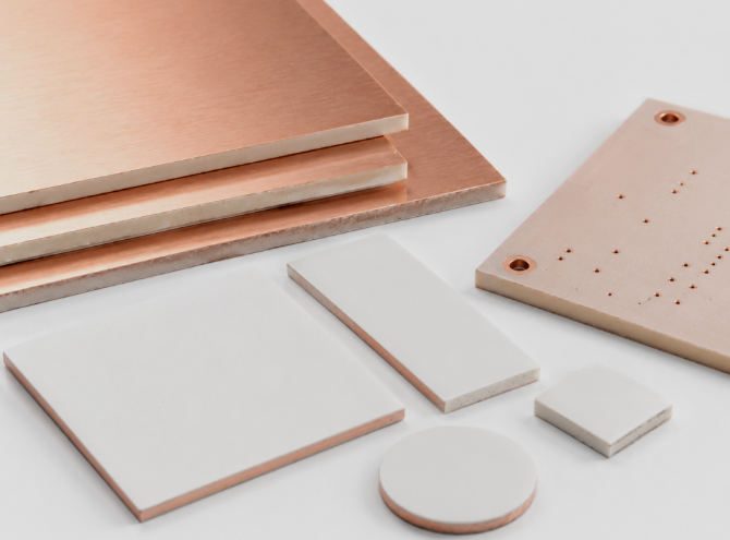
Three core electrical parameters define every RF laminate:
- Dielectric Constant (Dk or εr): Determines signal propagation velocity and trace geometry for a target impedance. Lower Dk means faster signal speed and wider traces for a given impedance.
- Dissipation Factor (Df or tan δ): Measures how much RF energy is lost as heat within the substrate. Lower Df = lower insertion loss.
- Thermal Stability: Glass transition temperature (Tg) and coefficient of thermal expansion (CTE) determine reliability during lead-free reflow and in field operation.
RF PCB Material Types: The Four Major Families
1. Hydrocarbon-Ceramic Laminates (Rogers RO4000 Series)
The RO4000 series—led by RO4350B and RO4003C—uses ceramic-filled hydrocarbon resin with woven glass reinforcement. The key advantage: they process identically to FR-4—same drilling, plating, etching, and lamination equipment. This eliminates the special handling required for PTFE materials and makes RO4350B the default choice for most commercial RF applications below 20 GHz.
RO4350B specifications at 10 GHz: Dk 3.48 (±0.05), Df 0.0037, Tg >280°C, CTE Z-axis 32 ppm/°C. It is widely used in 5G base stations, power amplifiers, GPS, WiFi 6E/7, and automotive radar up to ~20 GHz. RO4003C offers slightly lower loss (Df 0.0027) at Dk 3.38.
2. Ceramic-Filled PTFE Laminates (Rogers RO3000 Series)
The RO3000 series uses ceramic-filled PTFE composites with no glass weave reinforcement. These materials deliver ultra-low dielectric loss—RO3003 achieves Df 0.0013 at 10 GHz with Dk 3.00 (±0.04)—making them ideal for millimeter-wave applications above 20 GHz, including 77 GHz automotive radar, satellite communications, and microwave circuits.
However, RO3000 series materials require PTFE-specific fabrication processes: specialized drill bits, sodium-based desmear treatments, and surface activation for via plating adhesion. This increases cost and limits the number of fabricators capable of working with them.
3. Pure PTFE Laminates (Rogers RT/duroid, Taconic TLY)
Pure PTFE laminates—such as Rogers RT/duroid 5880 (Dk 2.20, Df 0.0009) and Taconic TLY-5 (Dk 2.20, Df 0.0009)—represent the lowest-loss RF PCB materials available. They are the only choice for frequencies above 40 GHz, including 77 GHz radar, satellite transceivers, and aerospace applications.
The trade-offs are significant: pure PTFE has a high CTE (150–300 ppm/°C) that creates via reliability challenges in multilayer builds, requires specialized fabrication, and costs 8–22× more than FR-4.
4. Thermoset High-Speed Laminates (Isola, Panasonic, Arlon)
Beyond Rogers, several other manufacturers offer competitive RF PCB materials:
- Isola Astra MT77 (Dk 3.00, Df 0.0017): Designed for 5G mmWave antenna arrays and automotive radar, with FR-4-compatible processing.
- Isola Tachyon 100G (Dk 3.02, Df 0.0021): Optimized for 100 Gbps+ high-speed digital and RF backplanes.
- Panasonic Megtron 7 (Dk ~3.37, Df 0.0012): Ultra-low loss with FR-4 process compatibility, ideal for 28+ GHz applications.
- Arlon 25N (Dk 3.38, Df 0.0025): Ceramic-filled PTFE with woven glass reinforcement.
- Taconic RF-35 (Dk 3.50, Df 0.0018): Ceramic-filled PTFE for power amplifiers and couplers.
RF PCB Material Comparison: Dk, Df, Cost & Processing
| Material Type | Representative Grade | Dk @ 10 GHz | Df @ 10 GHz | Process Compatibility | Cost vs FR-4 | Best Frequency Range |
|---|---|---|---|---|---|---|
| Standard FR-4 | FR-4 (Tg170) | 4.2–4.8 | 0.020–0.025 | Standard | 1× (baseline) | < 3 GHz |
| Hydrocarbon-Ceramic | Rogers RO4350B | 3.48 ±0.05 | 0.0037 | FR-4 compatible | 7–12× | 1–20 GHz |
| Hydrocarbon-Ceramic | Rogers RO4003C | 3.38 | 0.0027 | FR-4 compatible | 3× | 1–20 GHz |
| Ceramic-Filled PTFE | Rogers RO3003 | 3.00 ±0.04 | 0.0013 | PTFE process | 10–15× | 10–40 GHz |
| Pure PTFE | Rogers RT/duroid 5880 | 2.20 | 0.0009 | PTFE process | 15–22× | 40+ GHz |
| Pure PTFE | Taconic TLY-5 | 2.20 | 0.0009 | PTFE process | 10–14× | mmWave, 77 GHz radar |
| Thermoset High-Speed | Isola Astra MT77 | 3.00 | 0.0017 | FR-4 compatible | Medium-High | 5G mmWave, radar |
| Thermoset High-Speed | Panasonic Megtron 7 | ~3.37 | 0.0012 | FR-4 compatible | Medium-High | 28+ GHz |
How to Choose the Right RF PCB Material for Your Application
Step 1: Define Your Operating Frequency
This is the single most important decision criterion:
- < 3 GHz: FR-4 is often sufficient for cost-sensitive designs.
- 3–20 GHz: Rogers RO4350B or RO4003C—the FR-4-compatible sweet spot.
- 20–40 GHz: RO3003 or Isola Astra MT77—low-loss PTFE or thermoset alternatives.
- > 40 GHz: RT/duroid 5880 or Taconic TLY-5—pure PTFE is mandatory.
Step 2: Evaluate Your Loss Budget
At 10 GHz, a 50Ω microstrip on RO4350B measures ~0.38 dB/inch insertion loss, while the same geometry on FR-4 measures ~1.15 dB/inch. At 77 GHz, RO4350B becomes nearly unusable at 6–8 dB/inch, while PTFE remains workable at 2–3 dB/inch.
Step 3: Consider Fabrication and Cost Realities
Material choice is not just an electrical decision—it’s a manufacturing decision. RO4350B runs on standard FR-4 equipment, while PTFE materials require special handling that not every fabricator can support. Prototype PCB assembly with RO4350B is widely available; PTFE prototypes require specialized partners.
Step 4: Decide on Hybrid Stackups
Many production designs mix RF materials on outer layers with FR-4 on inner layers—a hybrid stackup that delivers most of the RF performance for a fraction of the all-Rogers material cost. This approach is particularly cost-effective for low-volume PCB assembly runs where material cost dominates.
PTFE vs. Hydrocarbon-Ceramic: The Critical Trade-Off
The most common material decision in RF PCB design is between Rogers RO4350B (hydrocarbon-ceramic) and PTFE-based laminates:
| Criterion | Rogers RO4350B | PTFE (RT5880, TLY-5) |
|---|---|---|
| Best for | 1–20 GHz applications | 20–77+ GHz applications |
| Dk @ 10 GHz | 3.48 (±0.05) | 2.1–2.2 (±0.02) |
| Df @ 10 GHz | 0.0037 | 0.0009–0.002 |
| CTE Z-axis | 46 ppm/°C | 150–300 ppm/°C |
| Fabrication | Standard FR-4 process | Special handling required |
| Cost vs FR-4 | 3–5× | 8–15× |
| Multilayer ease | Drop-in replacement | Challenging, limited fabs |
Bottom line: If your design operates below 20 GHz and needs multilayer integration, RO4350B wins on cost, reliability, and supply chain. If you’re pushing above 20 GHz and every 0.1 dB/inch matters, PTFE is the only path.
RF PCB Materials for Specific Applications
5G Sub-6 GHz Base Stations
Rogers RO4350B is the industry standard for 5G sub-6 GHz power amplifiers and active antenna units. Its FR-4 process compatibility enables high-volume PCB assembly at scale while maintaining the low loss and Dk stability required for beamforming arrays.
77 GHz Automotive Radar
RO3003 (Df 0.0013) and Taconic TLY-5 (Df 0.0009) are the preferred materials for 77 GHz radar sensors. The smooth copper surface and ultra-low loss tangent are critical for maintaining range and resolution in ADAS systems.
Satellite Communications
RT/duroid 5880 with Dk 2.20 and Df 0.0009 is the material of choice for space-grade RF circuits, where every decibel of loss directly impacts link margin.
High-Speed Digital + RF Hybrid Boards
Isola Tachyon 100G and Panasonic Megtron 7 bridge the gap between high-speed digital (100 Gbps+ backplanes) and RF performance, offering ultra-low loss with FR-4-compatible processing.
Common RF PCB Material Selection Mistakes
- Specifying “Rogers” without a grade: Rogers manufactures dozens of distinct materials across RO4000, RO3000, RT/duroid, and other families. “Rogers” is not a material—it’s a brand.
- Over-specifying PTFE for sub-20 GHz designs: PTFE costs 8–15× FR-4 and requires special fabrication. RO4350B delivers comparable performance below 20 GHz at half the cost.
- Ignoring process compatibility: Not every PCB fabricator can handle PTFE. Always confirm your PCB manufacturing partner’s capabilities before specifying PTFE materials.
- Forgetting about CTE mismatch in multilayer boards: PTFE’s high Z-axis CTE (150–300 ppm/°C) can cause via cracking during reflow—especially in boards with more than 6 layers.
Frequently Asked Questions About RF PCB Material Types
What is the most commonly used RF PCB material?
Rogers RO4350B is the most widely used RF PCB material. It offers Dk 3.48, Df 0.0037, processes like FR-4, and costs 3–5× standard FR-4.
What is the difference between RO4350B and RO3003?
RO4350B is a hydrocarbon-ceramic material that processes like FR-4 (Dk 3.48, Df 0.0037). RO3003 is a ceramic-filled PTFE material (Dk 3.00, Df 0.0013) that requires PTFE-specific fabrication. RO3003 has lower loss but higher cost and processing difficulty.
When should I use PTFE instead of Rogers hydrocarbon materials?
Use PTFE (RT/duroid 5880, Taconic TLY-5) for frequencies above 20 GHz where Df below 0.002 is mandatory. Below 20 GHz, RO4350B is usually the better choice.
Can I mix RF materials with FR-4 in the same board?
Yes—hybrid stackups with Rogers cores on RF layers and FR-4 elsewhere are common and cost-effective.
What RF PCB materials are compatible with standard FR-4 processing?
Rogers RO4000 series (RO4350B, RO4003C), Isola Astra MT77, and Panasonic Megtron 7 all process like FR-4.
How much do RF PCB materials cost compared to FR-4?
RO4350B: 3–5× FR-4; RO3003: 10–15×; RT/duroid 5880: 15–22×.
Key Takeaways: RF PCB Material Types
- RF PCB materials fall into four families: hydrocarbon-ceramic (RO4350B), ceramic-filled PTFE (RO3003), pure PTFE (RT/duroid, TLY-5), and thermoset high-speed (Astra MT77, Megtron 7).
- Frequency is the primary selector: <3 GHz → FR-4; 3–20 GHz → RO4350B; 20–40 GHz → RO3003/Astra MT77; >40 GHz → RT/duroid/TLY-5.
- RO4350B is the industry workhorse—FR-4 process compatible, Dk 3.48, Df 0.0037.
- PTFE delivers the lowest loss (Df 0.0009) but requires specialized fabrication and costs 8–22× FR-4.
- Hybrid stackups (RF materials on outer layers, FR-4 inside) reduce cost while maintaining performance.
- Always confirm your PCB manufacturing partner’s capabilities before specifying PTFE materials.
Need help selecting the right RF PCB material for your design? Our engineering team specializes in Rogers, Taconic, Arlon, and Isola RF laminates. Get a free material recommendation and DFM analysis—upload your stackup and get a expert review within 24 hours.
- AtlasPCB. (2026). Rogers PCB Material Guide: Complete overview of Rogers PCB materials including RO4000, RO3000, RT/duroid series. Retrieved from https://www.atlaspcb.com/blog/what-is-rogers-pcb-material/
- AtlasPCB. (2026). Rogers RO4350B vs PTFE for RF PCB: Material Selection Guide for 5G, Radar, and mmWave. Retrieved from https://www.atlaspcb.com/blog/rogers-4350b-vs-ptfe-rf-pcb-material/
- PCBSync. (2025). Rogers PCB Materials: Complete Guide to RO4000, RO3000, RT/duroid & All Series Laminates Compared. Retrieved from https://pcbsync.com/rogers-pcb/
- AtlasPCB. (2026). FR-4 vs Rogers PCB: Complete Material Selection Guide for RF and High-Speed Designs. Retrieved from https://www.atlaspcb.com/blog/fr4-vs-rogers-pcb-material-selection-rf-high-speed/
- AtlasPCB. (2026). RF PCB Cost Breakdown: Detailed pricing analysis of RF PCB fabrication costs. Retrieved from https://www.atlaspcb.com/blog/rf-pcb-cost-breakdown-rogers-high-frequency-laminate-pricing/
- NextPCB. (2026). RF PCB Manufacturing Guide: Material Selection, Impedance & DFM Best Practices. Retrieved from https://jp.nextpcb.com/blog/rf-pcb-manufacturer