Bringing Up A Signal Conditioner Evaluation Board
An evaluation board exists to answer a question that a datasheet cannot: how does this device behave when it is placed in a real channel? For a signal conditioner, whether that is a redriver, a retimer or a buffer, the answer depends on the launch into the package, the quality of the reference planes, the cables used and the way the measurement is set up. A well designed evaluation board removes most of that uncertainty by fixing the variables.
This article describes what a signal conditioner evaluation board typically provides, how to bring one up without damaging it, and how to get measurements that mean something.
Most of the errors made with these boards are not electrical. They are setup errors that produce a result nobody can reproduce.
What Is On The Board
The core of the layout is a set of high speed differential pairs connecting the device to coaxial connectors through a controlled impedance route. A four channel device will typically present eight input connectors and eight output connectors, arranged so that each differential input and its matching output can be measured independently. The transmission line structure used for those routes has to be consistent, because a mismatch at the SMA launch will appear in every measurement made through it.
Around the signal path sit the support circuits. There is a DC input, usually with a connector and a set of test points so that the supplies can be verified before the device is enabled, and there is a control interface for the configuration pins. Because the device may have several operating modes, the board normally provides switches or jumpers that set those pins, and the manual lists the combinations.
Understanding The Control Pins
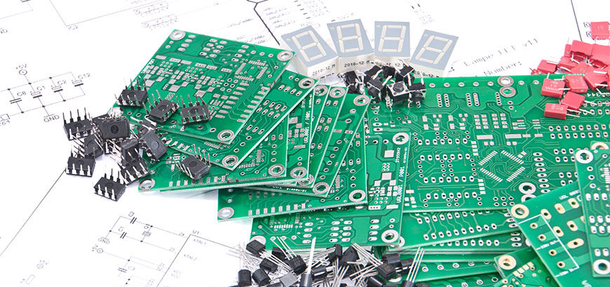
The control pins are where most of the ambiguity lives. A typical device has a small number of pins that select an operating mode by being tied to ground through a resistor, left floating, or tied to the supply, and the evaluation board exposes each of those states with a switch. A three pin arrangement with two positions each therefore offers several combinations, and only some of them are meaningful.
The pins are read at power up, so the setting has to be correct before the supply is applied. Changing a switch while the device is running may have no effect at all, which is a common source of confusion during a first session. Reading the pin table once and writing down the configuration that will be used saves considerable time later.
Bringing It Up Safely
The first power up should be done with the supply current limited to a value just above the expected draw. That way a reversed connection or a short on the board produces a supply that folds back rather than a device that burns. Before applying power, the board should be inspected under magnification for solder bridges, particularly around the fine pitch package.
The supplies should then be verified at the test points before the device is enabled, and the sequence of the rails should follow the order the data sheet specifies. Measuring a board that has been powered in the wrong order is a good way to destroy it and then conclude that the device is faulty. Once the rails are correct and the reference clock, if there is one, is running, the device can be enabled.
<img src="https://www.gopcba.com/wp-content/uploads/2026/09/167-1.jpg" alt="Eye diagram captured at the output of a signal conditioner” />
Setting Up The Measurement
Measurements on these boards are usually made in two stages. The first is a frequency domain measurement of the channel, using a network analyser to record insertion loss and return loss with the device in a known configuration. The cables and connectors used for the measurement are part of the channel, so their loss has to be measured and removed from the result, otherwise the device looks worse than it is.
The second stage is a time domain measurement, in which a pattern generator drives the differential input and an oscilloscope captures an eye diagram at the output. The quality of that measurement depends on the fixture: the cables should be matched, the connectors should be torqued consistently, and the reference plane for the probes should be the same one the board uses. The quality characteristics of the board itself show up directly in how repeatable the result is between channels.
What The Device Is Doing To The Signal
A signal conditioner compensates for the loss of the channel between a transmitter and a receiver. A redriver applies equalisation at its input and adjusts output amplitude and pre emphasis so that the waveform arriving at the far end is still open. A retimer goes further and recovers the clock, regenerating the data so that jitter does not accumulate along the link.
Both are evaluated in the same way on a bench, but the numbers that matter are different. A redriver is judged mainly on its equalisation range and on the jitter it adds itself, while a retimer is judged on its ability to restore an eye that has already closed. Knowing which category the part belongs to determines which measurements are worth making, and which of the control pin settings are worth the time to explore.
Interpreting What You See
The eye diagram shows the combined effect of the device and the channel. A closed eye at the output can be caused by the device, by the loss of the cables, or by an impedance discontinuity at a connector, and distinguishing between them requires the frequency domain data. If insertion loss is flat and the return loss is good, the channel is behaving and the closing eye belongs to the device or to its settings.
The control pin configuration is worth checking again whenever a result is unexpected. A device driving a longer pre-emphasis setting than intended will show a different eye, and a device in a bypass mode will show almost nothing at all. Comparing a measurement against the same measurement in a different mode is the quickest way to confirm that the board is doing what it was told.
Good Practice On The Bench
Three habits make the difference between data and noise. Record the configuration with every measurement, including the switch positions, the supply voltages and the cable types. Leave the cables connected in the same way between runs rather than reconnecting them for each setting, since the repeatability of a coaxial connection is better than the repeatability of a person. And handle the board with the same care as the device on it, because an evaluation board with a damaged launch will mislead every measurement made with it.
Where an improvement is needed at the board level, it is usually in the launch and the reference plane rather than in the components. gopcb builds controlled impedance boards and evaluation fixtures with documented stackups, and can supply the impedance verification data that improves the signal quality of a measurement setup.
FAQ
Why are the connectors on an evaluation board spaced so far apart? To keep the channels isolated and to give the cables room, which matters more than compactness when every channel is measured individually.
Does the cable loss have to be removed from the result? Yes, if the number is to describe the device. Measuring the cables on their own and subtracting their loss is the usual method.
Can the control pins be changed while the board is running? Some devices latch their configuration at power up, so the reliable procedure is to set the switches first and then apply power.