SMT Mounting Principle: Placement Machine Mechanics
The SMT mounting principle explains how a placement machine picks a component from its feeder, verifies its position, and places it exactly on the pad of a PCB. SMT stands for surface mount technology, and the mounting machine is the key equipment that performs the placement step in the electronic assembly process.
Surface mount technology is the most popular technology and process in the electronic assembly industry. Components are mounted directly on the surface of a printed circuit board, allowing smaller products and higher assembly density than through-hole methods.
This guide describes the structure and working principle of an SMT mounter and the alignment methods used to place components accurately.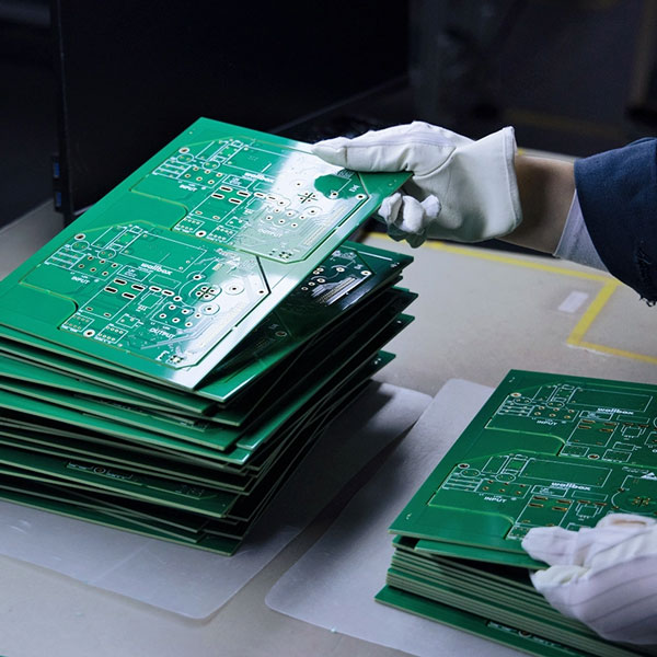
Role of the SMT Mounter
An SMT mounter is a precision industrial robot used to place electronic components, LED beads, and other surface mount parts on a PCB. It replaces manual placement and saves labor cost while improving productivity.
The complete SMT production line includes screen printing, component placement, and reflow soldering. Placement is the most important step in the surface mount process because it determines where every component will be soldered.
The placement machine is the most complex and most expensive production equipment on the line. Its accuracy directly affects the final electrical function of the board.
Combination of Technologies
An SMT mounter is not a simple mechanical machine. It combines electromechanical, optical, and computer control technologies into one integrated system.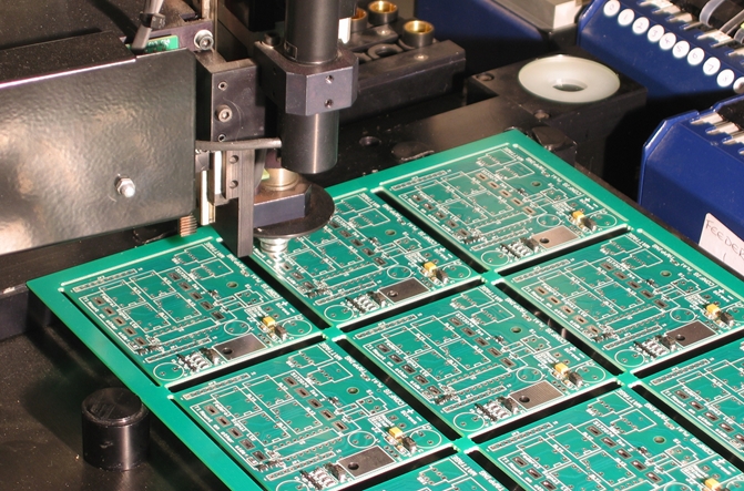
The machine can pick a component, measure its actual position, rotate it to the correct angle, and place it on the PCB. The complete cycle is repeated for every component on the board.
By absorbing, displacing, positioning, and placing, the machine installs SMC and SMD components quickly and accurately without damaging the component or the PCB.
The system is controlled by an industrial computer that sends instructions to the motion axes and processes data from the vision system.
Main Machine Components
A placement machine is composed of a frame, an X-Y motion mechanism, placement heads, component feeders, a PCB bearing mechanism, component centering devices, and a computer control system.
The X-Y motion mechanism moves the head to the required position. Power is transmitted by ball screws, and movement is guided by rolling linear guide rails.
The placement head carries one or more nozzles that pick and place components. Feeders present the components in a known position so the head can pick each part without searching.
The PCB bearing mechanism holds the board during placement, and the computer system coordinates all machine actions.
X-Y Motion Mechanism
Machine motion is mainly realized by the X-Y motion mechanism. A ball screw converts the rotation of the drive motor into precise linear movement.
A rolling linear guide rail creates the direction movement with low resistance. This type of transmission has a compact structure, high motion accuracy, and smooth operation.
The combination of ball screw and linear guide gives the machine the ability to stop at exact coordinates for every placement.
Mechanical accuracy depends on the quality of the screws, rails, bearings, and the calibration of the drive system.
Component Alignment Methods
There are three methods used to align a component before placement: mechanical alignment, laser alignment, and visual alignment.
Mechanical alignment uses a mechanical centering mechanism to push the component into a known position. It is simple but can damage fragile parts and is not accurate enough for fine-pitch devices.
Laser alignment measures the component body without touching it. It is fast but may not detect every lead defect.
Visual alignment uses a camera to inspect the component leads and calculate the exact placement correction. It provides the highest accuracy for modern SMT devices.
Vision and Marker Calibration
Important parts of the mounter are marked for machine vision, including the mounting spindle, moving and stationary lenses, nozzle support, and feeders.
Machine vision automatically calculates the coordinates of these markers and establishes the relationship between the machine coordinate system, the PCB coordinate system, and the component coordinate system.
With this relationship, the controller can calculate the precise movement required to place each component at the correct pad position.
Fiducial marks on the PCB provide an additional reference so the machine can compensate for board position and warpage.
Pickup and Vision Inspection
The placement head selects the nozzle required for the component package and moves to the corresponding feeder position. The nozzle then picks the component using vacuum.
The picked component is moved in front of a stationary camera or an onboard camera. The vision system recognizes the component and compares its image with the stored library data.
The system checks the body position, lead pattern, and rotation. If the component is missing, damaged, or incorrectly oriented, the machine discards it or stops for operator review.
Visual inspection at this stage prevents an incorrect component from being placed on the board.
Placement Operation
After the component has been inspected and aligned, the placement head moves to the programmed position on the PCB. The head lowers the component to the correct height and releases the vacuum.
The component is placed onto the solder paste, which holds it until reflow. The placement force and height are controlled to avoid shifting the paste or damaging the component.
If the machine uses soft-landing control, it senses the contact with the board and stops at the correct height automatically. This prevents placement errors on warped boards.
The industrial computer records the placement result and moves to the next component.
Factors Affecting Placement Accuracy
Placement accuracy depends on the motion system, vision calibration, component library, and board position. A small error in any reference can shift every component in one direction.
Ball screw wear, belt slip, or motor backlash can reduce the accuracy of the machine. Calibration should be performed regularly with a test board.
The component library should contain the correct body size, lead pitch, and height for every part. If the library data is wrong, even a perfect machine will place the component incorrectly.
The PCB should be flat and held firmly so that its position does not change during the placement sequence.
Placement Speed and Productivity
SMT mounters are used to improve productivity by placing components faster than manual assembly. High-speed machines use multiple heads or rotary turrets to increase throughput.
The placement cycle includes pickup, vision check, movement, and placement. Optimization of the pickup order reduces the total travel time.
Productivity should not be increased by reducing inspection quality. The machine must still verify every component before it is placed.
Balanced feeder arrangement and program optimization help the machine reach its rated speed without sacrificing accuracy.
A capable SMT PCB assembly service uses placement machines that are calibrated, programmed, and maintained for high placement accuracy.
The mounting process should be reviewed during PCB design and layout so that fiducials, pad size, and component spacing match the machine capability.
After placement and reflow, the board should be checked by PCBA testing and automated inspection to confirm that every part is in the correct position.
A professional PCB assembly partner should maintain the machine records and use quality management data to improve first-pass yield.
Placement Program Preparation
The placement program is usually generated from the PCB CAD file and the component BOM. The engineer imports the component coordinates, rotation angles, package types, and feeder assignments into the machine software. The program should then be optimized so that the head travels efficiently between pickups and placements.
Every component type used in the program must have a record in the machine component library. The record contains the body size, lead pitch, height, vacuum setting, and vision method. If a new package is introduced, the engineer must create a new library record and verify it on a sample board before full production.
The program should be checked for errors before the first board is run. A wrong coordinate, missing library record, or incorrect feeder station will create the same defect on every board until the operator corrects the program.
Calibration and Process Control
Machine calibration should be verified when the machine is installed, after major repair, and at regular intervals. Calibration checks compare the actual placement position with the programmed position using a test board or calibration target.
If the machine drifts, the operator may see all components shifted in one direction or rotated by the same angle. The calibration record helps the engineer decide whether the error comes from the motion system, the camera, the board holder, or the placement program.
Placement data should be combined with reflow and inspection data to control the complete process. A small increase in placement deviation can be detected before it creates opens or bridges after soldering. Statistical process control makes the improvement visible over time.
Conclusion
The SMT mounting principle is based on precise motion control, component recognition, and automated placement. The machine picks each part, checks its position, and places it on the correct pad.
Mechanical, laser, and visual alignment methods provide different levels of accuracy. Visual alignment is essential for fine-pitch and BGA components.
With a well-maintained mounter and a verified placement program, an SMT line can place components quickly and reliably for modern electronic products.