SMT Placement Equipment: What Each Machine in the Line Does
An SMT line is often described as a series of machines, but it is more useful to think of it as a chain of tolerances. Each station adds its own variation to the board, and the final yield depends on how those variations stack up against the solder joint’s process window. Understanding what each machine contributes, and which defects trace back to which station, is what makes a line controllable rather than merely busy.
Why the Sequence Matters More Than Any Single Machine
Solder paste is printed, components are placed into that paste, the assembly is reflowed and the result is inspected. Each step assumes the previous one left the board in a known state, and a problem at one station changes what the next is being asked to do. Paste printed too thin makes every downstream judgement harder, while a placement offset that would be harmless on a wide pad becomes a defect on a fine pitch part.
The practical consequence is that defect data has to be read backwards along the line. A solder bridge is not automatically a printing problem, and a missing component is not automatically a feeder problem. Correlating the defect with the position on the panel and the time of day is usually the fastest route to the cause.
Solder Paste Printing: Where Most Defects Begin
The printer deposits paste through a stainless steel stencil onto the pads, and the volume it leaves behind sets the solder joint height and the tendency to bridge. Aperture size, stencil thickness, squeegee pressure, separation speed and paste condition all move the result, which is why printing is the station most often implicated in defect Pareto charts.
Control comes from measurement rather than from judgement. An automated paste inspection step after printing quantifies volume and area for each pad, so a drift is caught before the components are placed on top of it. Our notes on stencil aperture and placement tolerance explain how aperture design interacts with the achievable placement accuracy of the rest of the line.

Pick and Place: Accuracy, Speed and Feeder Setup
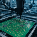
A modern placement machine positions tens of thousands of components per hour with a repeatability measured in tens of microns. What limits a real line is rarely the machine specification and usually the setup: a feeder that presents a part slightly off centre, a nozzle that has picked up a component at an angle, or a vision system that fails to recognise a part after a reel change.
Feeder and nozzle management therefore deserve as much attention as the placement head. Recording which nozzles and feeders are used for each product, and verifying them before a run rather than during it, removes a large share of the small stoppages that make a line miss its takt time. Where fine pitch devices are involved, a first article placement check against the paste image is worth the few minutes it costs.
Reflow: Profile, Zones and Atmosphere
Reflow turns the printed paste into a metallurgical joint, and the profile determines whether that happens cleanly. Preheat must activate the flux and bring the assembly up evenly, the soak must let the smaller parts and the larger parts approach the same temperature, and the peak must exceed the liquidus long enough to form a proper joint without cooking the laminate.
Zones and conveyor speed are the levers, and the profile should be verified with a profiler on a representative assembly rather than assumed from the oven display. Nitrogen atmosphere reduces oxidation and improves wetting on fine pitch assemblies, at the cost of gas consumption and a different wetting behaviour that can affect the appearance of the joint. Our comparison of lead-free and leaded solder covers how the alloy choice changes the window.
Inspection: What Each Station Catches
Optical inspection after reflow checks placement, polarity and the visible quality of joints. X-ray inspection looks under packages and inside barrels where light cannot reach, finding voids, hidden bridges and cracked plating. Electrical test then checks connectivity and function, which is the only step that confirms the assembly actually works rather than merely looking correct.
Each method catches a different class of defect, and none of them replaces the others. A board can pass optical inspection, show clean X-ray images and still fail in circuit because a joint is marginal rather than visibly defective. Our overview of SMT inspection methods describes how the three fit together in a production flow.
Handling, Storage and Line Balance
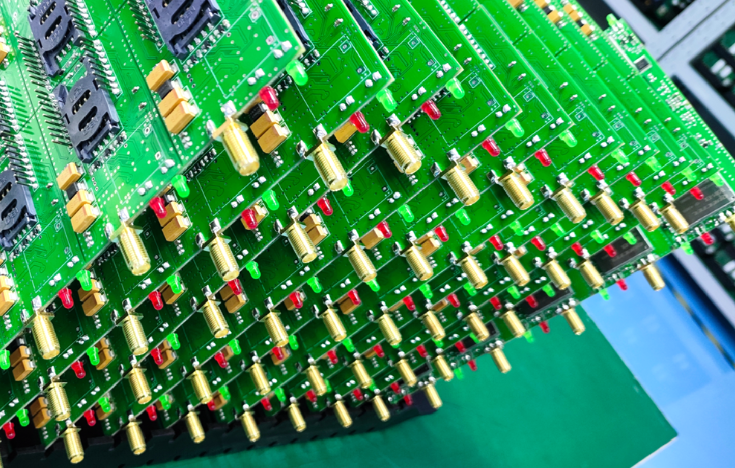
Between the stations, boards are handled more than at any other time in their life. ESD control, moisture sensitive device handling and simple cleanliness all matter here, and most of the damage is invisible until a batch fails electrical test. Components that have absorbed moisture must be baked and reflowed within their floor life, or they will delaminate at the peak temperature.
Line balance decides throughput. If the printer can supply boards faster than the placement machines can populate them, the printing station is not the constraint and improving it changes nothing. Identifying the actual bottleneck, and fixing that station first, produces more output than a general push on every machine in the line.
Changeover discipline is the other half of throughput. Every product change means new feeders, a new program, a new stencil and a new profile, and the time this takes is often underestimated when a line is quoted. Standardising feeder carts, keeping stencils stored with their program and documenting the changeover sequence turns an unpredictable hour into a repeatable routine. That predictability matters more than the peak speed of any single machine, because it lets the line be scheduled rather than merely hoped for.
Choosing Equipment for a Product Mix
The right equipment depends on the mix of products rather than on the fastest machine available. High mix, low volume work needs quick changeover, flexible feeders and simple programming, while a single high volume product rewards speed and automated verification. Buying for the wrong mix produces a line that is fast when it runs and idle while it is being set up.
Consider the smallest component you will place, the largest board you will build and the inspection you will need for both. Those three constraints define the practical capability of the line far more accurately than a headline placement rate, and they should be agreed with the assembly partner before the design is finalised.
FAQ
Which station causes the most defects? In most lines, solder paste printing contributes the largest share, because it sets the volume of solder for every joint. Placement errors are usually easier to detect and correct, while reflow problems tend to appear as a pattern across the whole panel rather than as isolated defects.
Is nitrogen reflow always better? It improves wetting and reduces oxidation, which helps on fine pitch and on assemblies with long thermal excursions. It also costs gas and changes the appearance of joints, so the benefit should be measured against the requirement rather than adopted by default. Many products achieve excellent yield in air.
How often should the reflow profile be verified? At least at the start of each product run and after any change to the oven, the conveyor or the assembly itself. A profile recorded once and reused indefinitely is a common way for a process to drift out of specification without anyone noticing until the defect rate rises.