As electronic products continue to become smaller, smarter, and more powerful, PCB assembly technology has evolved to meet increasingly demanding requirements for miniaturization, reliability, production efficiency, and electrical performance. Today, two major component mounting methods are widely used in electronics manufacturing: Surface Mount Technology (SMT) and Through-Hole Technology (THT).
Although SMT and THT assembly can both be used to mount electronic components onto a printed circuit board, they differ significantly in component structure, assembly processes, mechanical strength, production efficiency, cost, and application scenarios.
Understanding the difference between SMT vs THT is essential when selecting components and developing a reliable PCB assembly strategy. In many modern products, SMT provides the high-density and automated assembly capabilities required for compact electronic devices, while THT remains valuable for components that require greater mechanical strength, higher power handling, or easier manual replacement.
This guide explains surface mount technology, through-hole technology, their respective advantages and disadvantages, major differences, component types, applications, and how SMT and THT can be combined in mixed PCB assembly.
What Is Surface Mount Technology (SMT)?
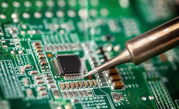
Surface Mount Technology (SMT) is a PCB assembly technology in which electronic components are mounted directly onto the surface of a printed circuit board rather than inserted through drilled holes.
Components used in SMT are known as Surface Mount Devices (SMDs). Typical SMD components include resistors, capacitors, inductors, diodes, transistors, integrated circuits, connectors, switches, and various semiconductor packages.
Unlike traditional through-hole assembly, SMT does not normally require component leads to pass through the PCB. Instead, solder paste is printed onto the PCB pads, components are accurately positioned by automated pick-and-place machines, and the assembly passes through a reflow soldering process to form permanent electrical and mechanical connections.
A typical SMT assembly process includes:
- PCB loading
- Solder paste printing
- Solder Paste Inspection (SPI)
- SMD component placement
- Pre-reflow Automated Optical Inspection (AOI)
- Reflow soldering
- Post-reflow AOI
- X-ray inspection when required
- Functional and electrical testing
Because the process is highly automated, SMT is particularly suitable for high-density PCB designs, small components, fine-pitch packages, and medium- to high-volume production.
Common SMT Components
Common SMD components include:
- SMD resistors
- SMD capacitors
- SMD inductors
- SMD diodes
- SMD transistors
- SMD LEDs
- SMD integrated circuits
- BGA packages
- QFP and QFN packages
- CSP packages
- SMD connectors
- SMD switches
- Crystal oscillators
- Voltage regulators
- Surface-mount transformers
Modern SMD packages are available in extremely small sizes, allowing designers to achieve high component density while reducing overall PCB dimensions.
Advantages of Surface Mount Technology
1. High Component Density
One of the most important advantages of SMT assembly is its ability to achieve very high component density.
Because SMD components do not normally require drilled through-holes, PCB designers can use more of the available board area for routing and component placement. Components can also be mounted on both sides of the PCB.
This makes SMT particularly suitable for:
- Smartphones
- Wearable devices
- IoT products
- Medical electronics
- Automotive electronics
- Communication equipment
- Industrial control systems
2. Miniaturized Electronic Products
SMD components are generally smaller and lighter than equivalent through-hole components. This enables manufacturers to develop thinner and lighter electronic products without sacrificing circuit functionality.
For applications where PCB space is limited, SMT technology makes it possible to integrate a large number of components into a compact board design.
3. High-Speed Automated Assembly
Modern SMT production lines can automatically place thousands of components per hour. Automated feeders, precision placement heads, vision systems, SPI, AOI, and reflow equipment provide consistent manufacturing performance.
Automation reduces dependence on manual component placement and helps improve:
- Production throughput
- Placement consistency
- Manufacturing repeatability
- Labor efficiency
- Production scalability
4. Excellent High-Frequency Performance
SMD components generally have shorter electrical paths and smaller lead structures than traditional through-hole components.
The reduced parasitic inductance and capacitance can benefit high-speed and high-frequency circuit designs. As a result, SMT is widely used in applications involving:
- High-speed digital signals
- RF circuits
- 5G communication
- Networking equipment
- Data processing systems
- Wireless devices
However, actual signal integrity depends on the complete PCB design, stackup, materials, routing, impedance control, component selection, and manufacturing tolerances.
5. Suitable for Double-Sided Assembly
Another major advantage of SMT PCB assembly is that SMD components can generally be placed on both sides of a PCB.
This enables designers to maximize the usable PCB area and increase functional density without significantly increasing board size.
6. Lower Production Cost at Scale
Although an SMT production line requires significant initial investment in equipment, the highly automated process can reduce labor requirements and improve production efficiency.
For medium- and high-volume production, SMT can provide competitive overall manufacturing economics through:
- Automated component placement
- Reduced manual handling
- High production throughput
- Efficient material utilization
- Standardized process control
- Reduced assembly time
Disadvantages of Surface Mount Technology
Despite its many advantages, SMT assembly also presents several challenges.
1. Higher Equipment Investment
A professional SMT production line requires specialized equipment, including solder paste printers, SPI systems, pick-and-place machines, reflow ovens, AOI systems, and potentially X-ray inspection equipment.
The initial capital investment can therefore be significant.
2. More Difficult Manual Rework
Very small components and fine-pitch packages can be difficult to inspect, remove, and replace manually.
Packages such as BGA and QFN can be particularly challenging because some or all solder joints are located underneath the component.
For these assemblies, professional rework equipment and inspection technologies may be required.
3. Thermal Process Requirements
SMT components and solder materials must withstand the thermal profile of the reflow process.
Incorrect temperature ramp rates, excessive peak temperatures, insufficient time above liquidus, or inappropriate cooling rates may result in soldering defects or component damage.
Therefore, reflow profile optimization is an important part of SMT quality control.
4. Limited Suitability for Certain High-Mechanical-Stress Components
Large connectors, transformers, relays, high-power components, and other mechanically stressed components may benefit from the additional mechanical support provided by through-hole mounting.
For these applications, THT assembly or mixed assembly may be more appropriate.
What Is Through-Hole Technology (THT)?
Through-Hole Technology (THT) is a PCB assembly method in which component leads are inserted through drilled holes in a printed circuit board.
The holes are typically plated through holes (PTHs), allowing electrical connections between PCB layers. After component insertion, the leads are soldered to the corresponding pads.
Depending on component type and production requirements, THT components can be assembled manually or using automated insertion equipment.
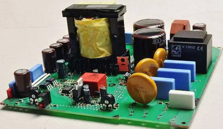
Typical through-hole components include:
- Large capacitors
- Transformers
- Relays
- Power resistors
- Connectors
- Switches
- Fuses
- Inductors
- High-power components
- Mechanically stressed components
Advantages of Through-Hole Technology
1. Strong Mechanical Connections
One of the most important benefits of through-hole assembly is mechanical robustness.
Because component leads pass through the PCB, the soldered connection provides mechanical anchoring in addition to the electrical connection. This makes THT suitable for products exposed to vibration, mechanical loading, frequent connector insertion, or physical stress.
2. Suitable for High-Power Applications
Many large through-hole components are available with higher voltage and current ratings than their miniature SMD counterparts.
THT is therefore frequently considered for:
- Power supplies
- Industrial equipment
- Motor control
- High-current circuits
- High-voltage circuits
- Power conversion systems
The actual suitability must always be determined according to the component’s electrical rating, thermal design, PCB material, and application requirements.
3. Easier Manual Assembly and Repair
The relatively large size and spacing of THT components make them easier to handle manually.
Technicians can often inspect, desolder, replace, and repair through-hole components more easily than densely packed SMD components.
This can be advantageous during prototyping, field service, and low-volume production.
4. Suitable for Rugged Applications
Because of their mechanical anchoring, through-hole components can be useful in equipment exposed to significant mechanical stress.
Applications may include industrial controls, power electronics, transportation electronics, and certain aerospace or defense systems where specific components require additional mechanical support.
Disadvantages of Through-Hole Technology
1. Lower Component Density
The drilled holes required for THT components consume valuable PCB area.
Component leads and clearance requirements also restrict routing space, making THT less suitable for highly compact, high-density PCB designs.
2. Larger PCB and Component Footprint
Through-hole components are generally larger than SMD components.
This can increase the overall size and weight of an electronic assembly, which is undesirable for many portable and miniaturized products.
3. More Complex Automated Assembly
Although automated THT insertion equipment exists, through-hole assembly generally requires more handling steps than SMT.
In mixed assemblies, manufacturers may need to coordinate SMT placement, reflow soldering, THT insertion, selective soldering, wave soldering, or manual soldering.
4. Higher Labor Requirements for Certain Products
Some THT components cannot be efficiently processed through a fully automated SMT line.
Manual insertion or manual soldering may therefore increase production time and labor costs, particularly for products with a large number of through-hole components.
SMT vs THT: Key Differences
| Comparison | SMT | THT |
|---|---|---|
| Mounting method | Components mounted directly on PCB surface | Leads inserted through PCB holes |
| Component size | Generally smaller | Generally larger |
| Component density | Very high | Relatively low |
| PCB space utilization | Excellent | More space required |
| Assembly automation | Highly suitable | Suitable depending on component and process |
| Production speed | Very high | Generally lower |
| Mechanical strength | Suitable for most applications but design-dependent | Strong mechanical anchoring |
| High-power applications | Available for many applications | Often advantageous for large power components |
| Repairability | More challenging for fine-pitch components | Generally easier |
| Double-sided assembly | Highly suitable | More restrictive |
| High-frequency applications | Generally advantageous | Depends on component and layout |
| Prototyping | Requires specialized assembly equipment for very small components | Convenient for manual prototyping |
| Typical applications | Consumer electronics, communications, medical, automotive, IoT | Power electronics, connectors, relays, transformers, rugged equipment |
The choice between SMT vs THT should not be based on one factor alone. Component availability, electrical requirements, mechanical stress, thermal performance, PCB dimensions, production volume, cost, inspection requirements, and serviceability should all be considered during PCB design.
SMT and THT Mixed Assembly
Modern electronic products often require both technologies rather than relying exclusively on SMT or THT.
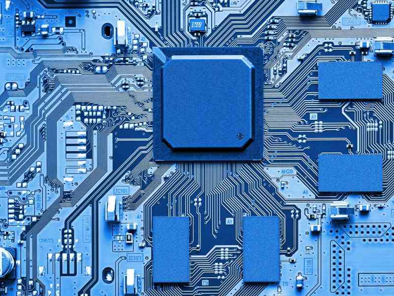
Mixed PCB assembly, also known as hybrid assembly, combines surface-mount and through-hole components on the same PCB.
For example, a control board may use:
- SMT components for microcontrollers and passive components
- BGA or QFN packages for high-density semiconductor devices
- THT connectors for mechanical strength
- Through-hole transformers for power conversion
- THT relays for switching
- Large capacitors for power circuits
This approach allows designers to take advantage of the miniaturization and automation of SMT while maintaining the mechanical and electrical advantages of selected THT components.
BGA Assembly and SMT
BGA assembly is an important branch of modern SMT manufacturing.
A Ball Grid Array package uses an array of solder balls underneath the package instead of conventional leads around its perimeter. This design allows manufacturers to achieve high I/O density while maintaining a relatively compact package footprint.
However, BGA solder joints are hidden beneath the component and cannot be fully verified using conventional visual inspection.
Professional BGA PCB assembly may therefore require:
- 3D SPI
- 3D AOI
- X-ray inspection
- Controlled reflow profiles
- Stencil optimization
- Accurate component placement
- PCB warpage control
- Detailed process traceability
SMT and THT Applications
SMT Applications
SMT technology is widely used in:
- Consumer electronics
- Smartphones and wearable devices
- IoT products
- Automotive electronics
- ADAS systems
- Medical devices
- Industrial automation
- Telecommunications equipment
- Networking equipment
- Computer hardware
- High-speed digital products
THT Applications
THT technology remains valuable in:
- Power supplies
- Industrial control systems
- High-current circuits
- High-voltage equipment
- Transformers and inductors
- Relays
- Large connectors
- Switches
- Mechanically demanding applications
Mixed Assembly Applications
SMT and THT mixed assembly is frequently used in complex electronic systems where different components have different mechanical, electrical, thermal, or manufacturing requirements.
How Kingda Supports SMT and THT PCB Assembly
As an experienced PCB manufacturer and PCB assembly service provider, Kingda provides integrated PCB manufacturing and assembly solutions covering the product development cycle from initial prototype validation to volume production.
Kingda can support customers with PCB prototyping, quick-turn PCB manufacturing, SMT assembly, THT assembly, and comprehensive PCBA manufacturing services.
1. One-Stop PCB and PCBA Manufacturing
Kingda integrates PCB manufacturing and PCB assembly capabilities to simplify supplier management and improve production coordination.
Customers can obtain PCB fabrication and assembly services through one manufacturing partner, reducing unnecessary communication and improving project efficiency.
2. SMT and THT Assembly Capabilities
Kingda supports both SMT assembly and THT assembly, allowing customers to select the appropriate technology according to component type, electrical performance, mechanical requirements, and production volume.
For complex products, Kingda can also provide mixed technology PCB assembly combining SMT and THT components on the same PCB.
3. Professional DFM Support
Manufacturing success begins with a manufacturable PCB design.
Kingda provides engineering support during the design and prototype stages, helping customers identify potential manufacturing issues related to:
- Component placement
- PCB stackup
- Pad and footprint design
- Solderability
- Component spacing
- Fine-pitch packages
- Thermal management
- Assembly accessibility
- Manufacturing tolerances
This DFM engineering review can help reduce manufacturing risks before production begins.
4. Automated Inspection and Quality Control
Reliable PCBA manufacturing requires inspection at multiple stages rather than relying only on final inspection.
Kingda’s quality-control approach can incorporate inspection and testing technologies such as:
- SPI
- AOI
- X-ray inspection
- Electrical testing
- Functional testing
- Visual inspection
- Process monitoring
- Traceability management
These processes help identify solder paste, component placement, solder joint, and hidden-joint defects at appropriate stages of production.
5. Prototype to Volume Production
Kingda provides manufacturing support across different production stages, including:
PCB Design → DFM Engineering Review → PCB Prototype Manufacturing → PCB Assembly → Inspection & Testing → Design Optimization → Small-Batch Production → Volume Manufacturing
This integrated workflow allows customers to move from initial design validation to stable production with fewer supplier transitions.
6. Industry-Oriented Manufacturing Solutions
Kingda’s PCB and PCBA solutions can support a broad range of applications, including:
- Industrial electronics
- Consumer electronics
- Automotive electronics
- Medical electronics
- Communication equipment
- IoT devices
- Power electronics
- Control systems
For projects requiring high reliability, component traceability, tight manufacturing tolerances, or complex assembly processes, the production strategy can be adjusted according to the specific product requirements.
How to Choose Between SMT and THT
When selecting between SMT and THT assembly, engineers should evaluate several key factors.
Choose SMT when:
- PCB space is limited
- High component density is required
- Components are small or fine-pitch
- Automated production is preferred
- Medium- or high-volume production is expected
- High-speed signal performance is important
- Double-sided component placement is required
Consider THT when:
- Components experience significant mechanical stress
- Large connectors or transformers are required
- High-current or high-power components are involved
- Components require strong mechanical anchoring
- Manual prototyping or frequent replacement is expected
Consider Mixed Assembly when:
- The PCB contains both fine-pitch SMDs and large THT components
- Mechanical strength is required for selected components
- Power components require through-hole mounting
- High-density digital circuits require SMT
- The product combines different electrical and mechanical requirements
Conclusion
SMT and THT are complementary PCB assembly technologies rather than competing technologies that must always be used separately.
Surface Mount Technology provides high component density, miniaturization, automated manufacturing, and strong support for modern high-speed electronic products. It is particularly suitable for compact and complex PCBs used in consumer electronics, communications, automotive, medical, industrial, and IoT applications.
Through-Hole Technology, meanwhile, remains important for components that require strong mechanical anchoring, higher power handling, larger physical structures, or easier manual repair and replacement.
For many modern electronic products, the most practical solution is mixed PCB assembly, combining SMT and THT technologies according to the requirements of individual components and the overall product design.
As an experienced PCB manufacturer and PCB assembly service provider, Kingda provides professional PCB prototype manufacturing, quick-turn PCB prototyping, SMT assembly, THT assembly, and PCBA manufacturing solutions to support customers from initial design verification through small-batch production and volume manufacturing.