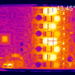
Thermal Fatigue: Solder Joint Fatigue Under Thermal Cycling
A solder joint fails under thermal cycling because the board and the component expand by different amounts and the joint has to absorb the difference. The damage accumulates with every cycle until a crack forms and propagates.
Why Expansion Mismatch Drives It
The expansion mismatch between the package and the board sets how much the joint has to deform. The plastic strain that results is concentrated at the point where the mismatch is greatest, which is usually the corner of a package.
The joint geometry decides how that strain is distributed. Our component reliability notes describe the design response.
What the Profile Changes
The temperature range, the ramp rate and the dwell all affect the life. The range sets the strain per cycle, and the dwell decides how much of that strain becomes creep damage rather than elastic deformation.
A profile with a long dwell is usually more damaging than a faster one with the same range. Our thermal cycling notes describe the design of the test.
Where the Crack Starts
The crack starts at the interface between the intermetallic layer and the bulk solder, and it propagates across the joint rather than through it. The failure is ductile at the start and becomes a fast fracture at the end.
The location is why the joint thickness matters. Our joint criteria notes describe the geometry that is preferred.
Acceleration and Extrapolation
A test result is extrapolated to service using an acceleration factor, and the factor depends on the mechanism. Using a factor that belongs to a different mechanism is the most common error in this area.
The extrapolation should state which mechanism it assumes. Our failure investigation notes describe how a field failure is classified.
Comparing Materials and Geometries
A comparison between two options is only valid if both are tested at the same profile and to the same failure criterion. A different criterion can change the ranking.
The criterion should be a measurable increase in resistance rather than a visible crack. Our yield analysis notes describe how the data is recorded.
Design Responses That Help
A thicker joint, a larger pad, an underfill and a lower modulus alloy all change the life. Each has a cost and each acts through a different mechanism.
Our underfill notes describe the option that changes the load path.
Verification
The verification is a profile recorded at the joint rather than at the chamber, a failure criterion based on resistance, and an extrapolation that states the mechanism it assumes.
Our thermal measurement notes describe the recording that goes with it.
Additional Considerations for This Build
Practical attention to dwell time pays for itself here, because it decides whether the finished board behaves as the drawing intended. Where the requirement is not stated on the fabrication drawing or in the assembly notes, the shop has to assume a default, and that default is rarely the value the design was simulated with. Stating dwell time explicitly, together with the tolerance that applies, removes the assumption and keeps the result predictable from batch to batch.
Process Control and Verification
On a design of this kind, expansion mismatch is the item that decides how the rest of the board is arranged. Keeping a sample from the panel turns a dispute into a measurement, because the same coupon can be re-examined by both parties without rebuilding the batch. Reviewing the design before the data is released is cheaper than correcting it after the panel is in the tank, because every step downstream inherits the decision made at the front end.
Documenting the assumption is part of the design work, and a short note on the drawing prevents a question that would otherwise arrive a day later and cost a day of schedule. The process window is set by the narrowest step in the flow, so an improvement anywhere else shows up as margin rather than as yield until that step is addressed.
A short note on the drawing about handling, storage or packaging is often worth more than an extra decimal place on a tolerance. Where a value sits close to a process limit, the drawing should say so, since the shop can then open the process window rather than working to a nominal figure that carries no tolerance.
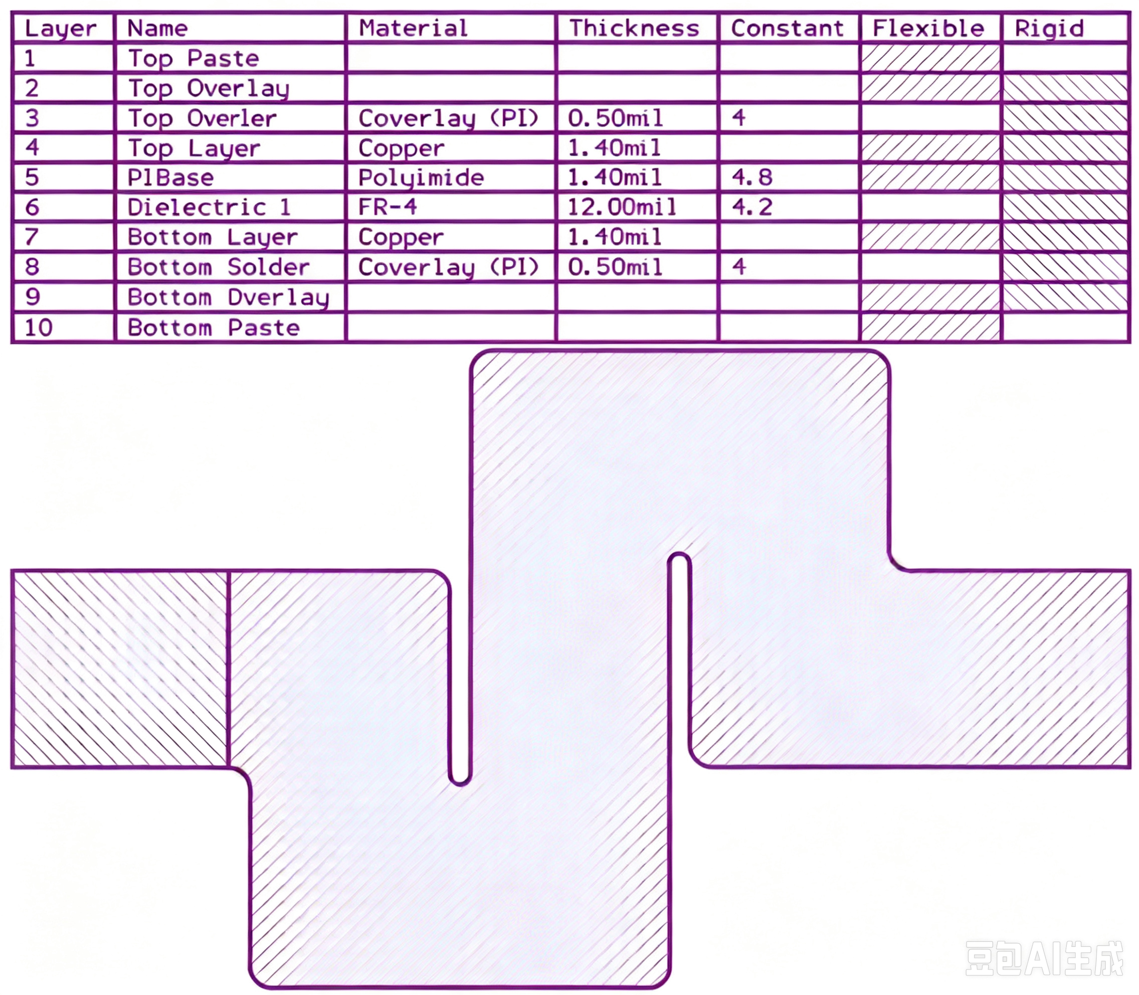
A stack-up that is drawn rather than described removes most of the ambiguity from a quotation, and it lets the fabricator price the board against the dielectric and copper weights that will actually be used. Where the requirement is not written down, the shop supplies its own default, and the default is chosen for the process rather than for the design.
The measurements that matter are the repeatable ones: conductor width and spacing, annular ring, finished hole size, plating thickness and surface finish are all verifiable on a coupon that travels with the panel.
Process Control and Verification
On a design of this kind, expansion mismatch is the item that decides how the rest of the board is arranged. Keeping a sample from the panel turns a dispute into a measurement, because the same coupon can be re-examined by both parties without rebuilding the batch. Reviewing the design before the data is released is cheaper than correcting it after the panel is in the tank, because every step downstream inherits the decision made at the front end.
Documenting the assumption is part of the design work, and a short note on the drawing prevents a question that would otherwise arrive a day later and cost a day of schedule. The process window is set by the narrowest step in the flow, so an improvement anywhere else shows up as margin rather than as yield until that step is addressed.
A short note on the drawing about handling, storage or packaging is often worth more than an extra decimal place on a tolerance.
Process Control and Verification
On a design of this kind, expansion mismatch is the item that decides how the rest of the board is arranged. Keeping a sample from the panel turns a dispute into a measurement, because the same coupon can be re-examined by both parties without rebuilding the batch. Reviewing the design before the data is released is cheaper than correcting it after the panel is in the tank, because every step downstream inherits the decision made at the front end.
Documenting the assumption is part of the design work, and a short note on the drawing prevents a question that would otherwise arrive a day later and cost a day of schedule.
A first article check confirms that the process and the drawing agree on the points listed above, and that the coupon data supports the values used in the design.
Where a measurement falls outside the expected window, the sample is retained so that the cause can be established before the balance of the batch is released.
FAQ
Is a larger joint always better? A thicker joint generally lasts longer under cycling, but the joint height is limited by the pad geometry and by the assembly process.
Does underfill always help? It changes the load path and it can transfer stress to the package, which is why the combination has to be tested rather than assumed.
What does gopcb provide for thermal fatigue work? We provide a test profile with the range, ramp and dwell stated, a failure criterion based on resistance rather than appearance, a sample size that supports the comparison being made, an extrapolation that names the mechanism, and a measured joint profile at the interface.