



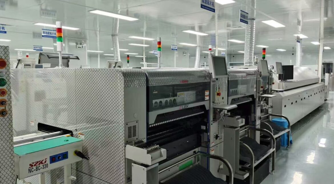
Stencil Aperture Misalignment: Finding Print Drift Fast
Stencil aperture misalignment is a lateral offset between the aperture in the stencil and the pad on the board at the moment the squeegee passes. Typical limits sit near 25 um for fine pitch work, and the defect only becomes visible when the deposit lands partly off the pad, so the printer can be drifting for hours before anyone notices.
Because the paste deposit is the input to every later stage, the offset propagates into placement, reflow and inspection. Tracking down the source means separating the three things that move relative to each other: the board, the stencil and the machine axes that are supposed to hold them in agreement.
What Counts as Aperture Misalignment
Misalignment is measured as the distance between the centre of the printed deposit and the centre of the intended pad, in the X and Y directions. It differs from the aperture being cut in the wrong place on the stencil, which is a data error, and from a deposit that is the right size but the wrong shape, which is usually a release problem.
A useful working limit is a quarter of the aperture width and never more than 50 um. On a 0.15 mm wide aperture, 25 um of offset already moves the deposit far enough that the paste can bridge to a neighbouring pad after reflow, because the paste spreads as it wets the copper.
Sources in the Printer Motion System
The print head moves in X, Y and theta, and each axis has a repeatability budget. Backlash in a worn lead screw, a loose tooling pin, or a servo that has developed following error will all produce a repeatable offset in one direction, which is the signature that separates a mechanical fault from a random one.
Squeegee pressure and speed influence the same result from the other side. Heavy pressure deflects the stencil into the apertures and drags it across the board, shifting the deposit with the stroke. Pressures in the range of 4 to 8 kg per 500 mm of squeegee length, adjusted until the stencil is wiped clean without being driven into the board, are the usual starting window.
Fiducial Recognition and Board Location
The printer positions the board by finding fiducials and then applies the stencil offset from that coordinate frame. A fiducial that is partly covered by solder mask, too close to a copper plane, or seen at a grazing angle of illumination will be located at the wrong centre, and every aperture on the panel inherits that error.
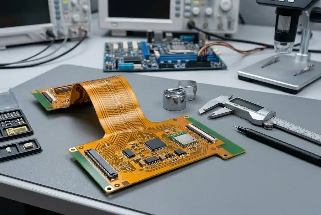
Consistency of fiducial contrast across the panel matters as much as the fiducial itself. If one of the two global fiducials is poorly defined, the machine may find its mark with a fraction of a pixel of bias, and the resulting angular correction tilts the whole stencil relative to the board rather than translating it.
Stencil Tension, Frame and Cleaning Effects
A stencil that has lost tension sags between the squeegee strokes and does not return to the same position each cycle. Tension in the range of 35 to 50 N per cm keeps the foil flat under the blade, and a foil that has relaxed below that range is replaced rather than re-tensioned in most shops.
Wiping is part of the same system. Vacuum wipe, solvent wipe and paper feed all move the stencil slightly, and a wipe station that has drifted off centre can nudge the foil in its frame clamps. The check is simple: print a test board, wipe, print again, and compare the two deposits. Board location starts long before the printer, with the tooling hole registration that also fixes the panel in drilling and routing.
Measuring Deposit Offset with SPI
Solder paste inspection is the fastest way to quantify misalignment, because it reports the X and Y offset of each deposit rather than a pass or fail for the panel. A histogram of offsets across the board shows a systematic shift as a narrow peak away from zero, while random variation shows up as a wide distribution around it.
The trend across a shift matters more than a single panel. If the mean offset moves in one direction as the printer warms up, the cause is thermal; if it steps after a squeegee change, the cause is the blade or its mounting. Either way the paste inspection data has already proved where the error sits before anyone looks at the machine.
What a Small Offset Does to the Deposit
An offset deposit still holds most of its volume, so the defect is not immediately a volume failure. The change is in where the paste sits relative to the pad. Paste that overhangs the pad on one side has less copper to wet on that side, so the fillet forms unevenly and the joint can pull the component off centre as it solidifies.
On a narrow pitch the overhang also reduces the gap to the next deposit. Two apertures that each shift outward by 20 um can leave the paste from adjacent pads in contact after reflow, which is a bridge that will be found only at the end of the line. That interaction is why aperture geometry and alignment have to be reviewed together.
Thermal Expansion and Board Growth
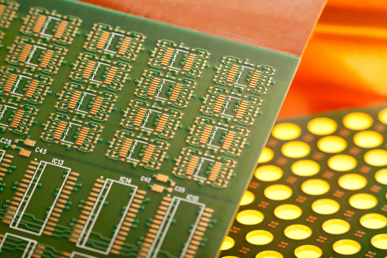
A stencil and a board expand at different rates, and both change dimension with the temperature of the room and of the machine. A 500 mm panel of FR4 type laminate grows by roughly 0.05 mm over a 10 degree rise, which is already twice the alignment tolerance that fine pitch work allows.
Where the printer runs a heated chamber or a hot board from a previous process, that growth is predictable and can be compensated by a programmed offset. It should be compensated from measurement rather than from a guess, because the laminate, the copper distribution and the direction of the weave all influence how much the panel actually moves.
Correcting Misalignment the Right Way
The offset can be programmed into the machine as a deliberate correction, and this is legitimate when it is measured and recorded. It becomes dangerous when it is used to hide a mechanical fault, because the fault keeps moving and the correction has to be re-tuned every shift until the printer finally fails.
Before adjusting the offset, confirm the stencil itself is flat and correctly located on its tooling pins, that the fiducials are legible, and that the board is clamped without distortion. If a correction is still needed, apply it in the direction that reduces the error by the measured amount, then re-measure rather than assuming the change landed exactly.
Verification Routine and Records
A workable routine is to print a first article at the start of the run, measure deposit offsets on all four corners of the panel, and then repeat the measurement after any change of paste lot, stencil, squeegee or product. Corner to corner comparison catches an angular error that a centre of panel reading would average away.
Recording the numbers, with the machine settings and the stencil identification, turns alignment from a running argument into a trend. When a panel later fails for bridging or a tombstone, the record shows whether the printer was drifting at the time, which is often the difference between finding the cause and replacing parts at random. Bridging that survives to the end of the line is normally caught by automated optical inspection, but the offset that created it is a printing problem and is cheaper to fix at the printer. The assumption to avoid is that a stencil aperture area ratio within limits guarantees the deposit lands where it was intended.
FAQ
How much stencil aperture misalignment is acceptable? A quarter of the aperture width, and never more than 50 um, is a practical working limit. Below 25 um most fine pitch assemblies reflow without difficulty, while above that the risk of bridging and uneven fillets rises quickly.
Can a printer offset be used to correct misalignment? Yes, when the offset comes from a real cause such as a known machine bias and is measured after the change. Using it to compensate for worn mechanics hides a fault that will continue to grow and eventually fall outside the correction range.
Why does alignment drift as the printer warms up? Frames, stencils and boards expand as the machine reaches operating temperature, and the three expand at different rates. A warm up print and a steady state print compared on the same panel will show whether thermal growth is a factor in the process.



1 Comment
Stencil Aperture Wall Angle: 6 Rules For Paste Release
[…] the wall specification together in the stencil file. When the tool is re-ordered, records such as stencil aperture misalignment should travel with it so the second stencil matches the first. Matching a re-ordered tool to the […]