Tantalum Capacitor SMT Assembly: Polarity, Soldering and Design Guide
What Makes Tantalum Capacitors Special for Surface Mount Boards
A tantalum capacitor is an electrolytic capacitor that uses tantalum metal as the anode and a solid manganese dioxide or conductive polymer electrolyte. Unlike ordinary aluminum electrolytic capacitors, the solid construction gives it a very high capacitance per unit volume, a low equivalent series resistance (ESR), stable temperature behavior and a long working life. These properties make it one of the most dependable component choices for dense printed circuit boards, and it is used in nearly every category of modern electronics.
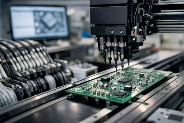
On an SMT line the same qualities translate into practical benefits. A SMT PCB assembly process can place hundreds of small tantalum parts quickly because they are supplied as standard surface mount packages with flat terminations. They do not need lead forming or through hole preparation, so they fit the fully automated flow from solder paste printing to reflow and inspection.
This guide explains how tantalum capacitors behave in circuits, where they are used, how to identify polarity during placement, how to solder them safely and which checks keep them reliable in volume production. The goal is to help design and manufacturing teams avoid the classic failure modes that appear when a good component is handled incorrectly.

Key Electrical Characteristics of Tantalum Capacitors
Tantalum capacitors are valued for four electrical characteristics. First is capacitance density: a tantalum part delivers far more microfarads than a ceramic capacitor of the same case size, which matters when bulk energy storage must fit in a small footprint. Second is low ESR and stable impedance, which reduces ripple voltage and heat generation in power circuits. Third is excellent temperature stability; the capacitance value and leakage current remain predictable from cold storage to hot running conditions. Fourth is long life, because the solid electrolyte does not dry out the way wet electrolytic capacitors do.
Designers must still respect two limits. Tantalum capacitors are polarized, and they are sensitive to overvoltage and surge current. A common design rule is to derate the working voltage to fifty percent of the rated voltage, and for higher reliability applications some companies derate to sixty percent or more. Applying this rule prevents most field failures, because a tantalum capacitor stressed beyond its voltage rating can fail into a short circuit rather than opening like a film capacitor.
Where SMT Tantalum Capacitors Are Used in Real Products
Because of their size and stability, tantalum capacitors appear wherever power quality matters inside a small space. Typical applications include input and output filtering on DC-DC converters, decoupling of processor core voltages, energy storage for momentary load steps, signal coupling and timing circuits, and hold-up capacitance for real time clocks. Portable electronics, laptops, tablets, networking equipment, servers, automotive electronic control units and base stations all rely on them.
The choice between tantalum, ceramic and aluminum capacitors depends on the circuit position. Ceramic capacitors cover high frequency decoupling with small values, aluminum electrolytic capacitors provide very large bulk capacitance at low cost, and tantalum capacitors fill the middle ground where volumetric efficiency, stable ESR and long life are required. In power management circuits the tantalum part is often the most cost effective way to obtain a large capacitance in a thin profile.
Advantages of Tantalum Capacitors in SMT Production
From a manufacturing point of view, tantalum capacitors are an assembly friendly component. Standard case sizes from small 0603 style parts up to larger EIA 7343 packages are easy to feed, pick and place with normal nozzles. The flat terminations allow a reliable solder joint with standard SAC305 lead free solder, and the parts survive the normal reflow thermal exposure when the profile is controlled.
Because the component body is solid and the terminations are robust, placement pressure can be applied without cracking the part, unlike some ceramic capacitors that are sensitive to mechanical stress. The polarity marking is molded into the body, which helps operators and automated optical inspection verify orientation. A well controlled line can therefore run tantalum capacitors at high speed with very low defect rates, and mixed technology boards that combine through hole and surface mount parts are handled in the same PCB assembly flow.
Limitations and Risks to Design Around
The main disadvantages are cost, polarity, and voltage sensitivity. Tantalum ore is scarce and refining is complex, so the parts cost more than ceramic or aluminum alternatives of similar ratings. Polarity must always be respected; a reversed tantalum capacitor can overheat and fail. Overvoltage and excessive inrush current are the most common causes of premature failure, and the failure mode is usually a short that can damage neighboring circuitry if the board has no protection.
These risks are manageable. Derating the applied voltage, limiting surge current with a small series resistor when charging from a low impedance source, and adding a fuse or current limit where the application is safety related are standard mitigation techniques. Circuit designers who follow the vendor derating guidelines and review the maximum ratings at the highest operating temperature will rarely see tantalum failures in the field.
Polarity Marking and Placement Rules for SMT Tantalum Capacitors
Polarity identification is the most important operator skill when working with components procurement and assembly. The positive terminal of a molded tantalum capacitor is marked with a colored stripe or a plus symbol on the body, while the negative terminal is usually unmarked. This is the opposite of many aluminum electrolytic capacitors, where the stripe indicates the negative side, so assemblers must check the datasheet rather than assume.
The printed circuit board also carries markings. A plus sign on the silkscreen, a notched pad shape, or a square pad instead of a round pad indicates the positive pad. The assembly drawing and the pick and place program must agree with the board markings, because a component rotated by one hundred eighty degrees during programming will produce a reversed part that may pass visual inspection until power is applied.
Good practice on the line includes a first article check before every batch, comparison of the feeder reel label with the bill of materials, and an orientation check after the first placement of each new part number. Placement machines should be programmed with the correct rotation angle for the case style, and nozzles must be sized to the body width so the component is not nudged during placement.
Reflow Soldering Profile and Handling Requirements
Tantalum capacitors tolerate reflow soldering well when the temperature profile stays inside the recommended window. For lead free assembly the typical recommendation is a peak temperature of two hundred forty to two hundred sixty degrees Celsius with time above liquidus kept as short as the solder paste allows. Excessive peak temperature or prolonged time above liquidus adds thermal stress to the component and can degrade the internal connections.
The parts also have moisture sensitivity levels, usually MSL 2 or MSL 3 for molded tantalum capacitors. Once the moisture barrier bag is opened, the floor life is limited, and if the exposure time is exceeded the parts must be baked before soldering according to the manufacturer instructions. Baking at the recommended temperature and duration removes absorbed moisture and prevents the internal cracking that otherwise appears during reflow.
During PCBA testing and handling, operators should avoid mechanical shock to the body and should never rework a tantalum capacitor with excessive heat. Hand soldering with a controlled temperature iron and a short dwell time is acceptable for prototypes, but mass production should use the standard reflow profile. Sudden thermal shock, such as moving a hot board directly into cold cleaning liquid, should also be avoided.
Quality Control and Inspection After Assembly
Automated optical inspection (AOI) is the first line of defense after reflow. The AOI program checks that the capacitor is present, correctly oriented with the polarity stripe matching the board marking, and centered on its pads with an acceptable solder fillet. X-ray inspection adds confidence for boards with components on both sides or where the terminations are partially hidden.
Incoming quality control is equally important. Counterfeit or relabeled tantalum capacitors are a real problem in the electronics market, so parts should be sourced from authorized distributors or trusted contract manufacturers with a verified supply chain. Sample testing of capacitance, ESR, leakage current and voltage rating at incoming inspection protects the whole production run from a bad batch.
Design for Manufacture Checklist for Tantalum Capacitors
A short checklist keeps the design manufacturable. Use the recommended land pattern from the package drawing, place the part away from high stress board areas and board edges, and allow enough clearance for the nozzle and the vision system. Keep the applied voltage below seventy percent of rating at all temperatures, respect the ripple current rating, and avoid placing tantalum capacitors close to hot components unless the temperature rise is included in the derating calculation.
Document the polarity convention on the assembly drawing so the PCBA factory and the test team read the same standard. When the design is finished, sharing the complete bill of materials with approved alternates helps turnkey PCB assembly partners procure the correct parts and avoid unauthorized substitutions.
How gopcb Supports Reliable Tantalum Capacitor Assembly
gopcb runs the complete chain under one roof, from PCB design and layout review to component sourcing, surface mount production and final testing. Our engineers check polarity markings, pad designs and derating during the DFM review, our feeders and placement programs are verified against the assembly drawing, and AOI plus functional testing confirm every board before shipment.
Whether you need a few prototype boards or high volume production with tight quality requirements, send gopcb your design files and bill of materials for a quotation. We will help you select the right tantalum capacitor ratings, assemble them with a controlled process and test the finished PCBs so your product performs reliably in the field.