As electronic products continue to become smaller, lighter, and more highly integrated, conventional rigid circuit boards are sometimes unable to provide enough flexibility for complex mechanical structures. At the same time, using separate rigid and flexible circuit boards can increase connectors, assembly steps, and potential points of failure.
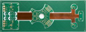
A Multilayer Rigid-Flex PCB combines rigid and flexible circuit structures into one integrated circuit board. By combining rigid sections with flexible sections through specialized manufacturing processes, this technology provides both mechanical stability and controlled flexibility.
Compared with conventional rigid PCBs, a Rigid-Flex PCB can simplify interconnections, reduce the number of connectors, save assembly space, and improve system-level reliability.
What Is a Multilayer Rigid-Flex PCB?
A Multilayer Rigid-Flex PCB is a circuit board that integrates multiple rigid PCB layers with one or more flexible circuit sections within the same interconnected structure.
The rigid portions provide mechanical support for components, connectors, mounting features, and other relatively fixed structures. The flexible portions allow the circuit to bend or fold around mechanical obstacles.
The basic concept can be understood as:
Rigid section + Flexible section + Integrated multilayer interconnection
Instead of connecting separate rigid and flexible boards with cables or connectors, the two structures are manufactured as one integrated PCB assembly.
This approach can be especially valuable when the electronic system has:
- Limited installation space
- Complex three-dimensional packaging
- Moving or folding components
- High connector density
- Strict weight requirements
- High reliability requirements
Structure of a Multilayer Rigid-Flex PCB
The construction of a Rigid-Flex PCB varies according to the application and manufacturer process.
A typical structure may include:
- Copper layers
- Polyimide flexible dielectric layers
- Flexible copper-clad laminate (FCCL)
- Flexible coverlay
- Adhesive layers where required
- FR-4 or other rigid dielectric materials
- Prepreg
- Solder mask
- Surface finish
- Stiffeners
- Plated through-holes and microvias where applicable
The rigid and flexible sections do not necessarily use identical material stacks.
This is one of the major differences between a conventional Multilayer PCB and a rigid-flex construction.
Materials Used in Multilayer Rigid-Flex PCBs
Material selection has a significant influence on the electrical, mechanical, and thermal performance of a Multilayer Rigid-Flex PCB.
Polyimide
Polyimide is one of the most widely used dielectric materials for flexible circuits.
It provides:
- Good flexibility
- Good thermal resistance
- Good dimensional stability
- Good electrical insulation
- Suitability for dynamic or static flex applications when properly selected
The exact polyimide system should be selected according to the required bending behavior, temperature exposure, thickness, and manufacturing process.
Copper
Copper forms the conductive layers of the circuit.
Flexible circuits may use different copper constructions depending on the application, including rolled-annealed copper and electrodeposited copper.
For applications involving repeated dynamic bending, copper type and grain structure can be particularly important.
FR-4 and Other Rigid Materials
Rigid sections may use FR-4 or other appropriate PCB laminate systems.
The rigid material provides mechanical strength for:
- Component mounting
- Connectors
- Screws and mounting holes
- Stiff structural areas
- Heat-generating components
The material system should be selected according to electrical performance, thermal requirements, reliability, and manufacturing compatibility.
Prepreg and Bonding Materials
Prepreg and other bonding systems can be used in the rigid portions of multilayer structures.
The actual lamination system depends on the rigid-flex stackup and manufacturing process.
Therefore, it is not accurate to assume that one specific bonding material is used in every rigid-flex PCB.
Why PP Is Not Simply the Standard Material for Rigid-Flex PCB Insulation
The original description may suggest that PP, or polypropylene, is a standard insulating layer between flexible layers.
In practical PCB Manufacturing, this description is too broad.
Rigid-flex PCBs typically use material systems specifically developed for rigid and flexible regions. Flexible areas commonly rely on polyimide-based dielectric materials and coverlay systems, while rigid areas may use FR-4-type laminates and prepreg.
The exact material combination depends on:
- Number of layers
- Bend requirements
- Lamination structure
- Temperature requirements
- Electrical performance
- Mechanical requirements
- Manufacturing technology
Therefore, material selection should be based on the complete stackup rather than assigning a single material to all insulating layers.
How Multilayer Rigid-Flex PCBs Are Manufactured
The manufacturing process for a Multilayer Rigid-Flex PCB is more complex than that of a conventional rigid multilayer board.
A typical process may include:
- Material preparation
- Flexible circuit fabrication
- Inner-layer imaging and etching
- Registration and inspection
- Layer stacking
- Rigid-flex lamination
- Drilling or laser drilling where applicable
- Desmear and copper plating
- Outer-layer imaging
- Circuit pattern formation
- Solder mask or coverlay processing
- Surface finishing
- Profile routing
- Electrical testing
- Dimensional and visual inspection
- Final testing and packaging
The exact process flow varies according to the rigid-flex construction.
Rigid and Flexible Regions Require Different Design Considerations
One of the most important characteristics of a Rigid-Flex PCB is that different regions of the same board may have different mechanical requirements.
The rigid area needs to provide mechanical support.
The flexible area needs to withstand bending without excessive stress on the copper and dielectric materials.
Therefore, designers should define rigid and flexible zones clearly during PCB Design.
The flexible region should generally avoid unnecessary components, large solder joints, and structures that could create excessive mechanical stress unless the design specifically supports them.
Bend Radius and Flexibility
Bend radius is one of the most important parameters in FPC and rigid-flex design.
The allowable bend radius depends on factors such as:
- Overall flex thickness
- Copper type
- Number of copper layers
- Static or dynamic bending
- Bend direction
- Material construction
- Required cycle life
A thicker multilayer flex section generally requires a larger bend radius than a thin single-layer flex circuit.
For dynamic applications involving repeated movement, the design should be evaluated using the actual bending conditions rather than relying on a generic bend-radius value.
Static Flex vs. Dynamic Flex
Not every Flexible PCB application requires repeated movement.
Static Flex
Static flex refers to applications where the flexible section is bent during assembly or installation and then remains relatively stationary.
Examples include:
- Folded internal interconnects
- Compact device connections
- Camera modules
- Display connections
- Fixed three-dimensional assemblies
Dynamic Flex
Dynamic flex is designed for repeated bending or movement.
Examples may include:
- Hinges
- Moving mechanisms
- Folding electronic devices
- Robotics
- Motion-control systems
Dynamic applications require much more careful consideration of copper structure, bend radius, flex thickness, neutral axis, support structures, and expected bending cycles.
Advantages of Multilayer Rigid-Flex PCBs
1. Reduced Connector Count
A major advantage of a Multilayer Rigid-Flex PCB is that flexible sections can directly connect different rigid areas.
This can reduce the need for:
- Board-to-board connectors
- Flexible cables
- Additional wiring
- Mechanical interconnects
Fewer interconnections can simplify assembly and potentially improve system reliability.
2. Space Saving
Rigid-flex structures can be folded into three-dimensional shapes.
This allows engineers to use available enclosure space more efficiently.
Instead of forcing all components onto a flat PCB, the circuit can follow the mechanical structure of the product.
This is particularly useful for compact electronic devices.
3. Weight Reduction
Replacing separate boards, cables, and connectors with an integrated rigid-flex structure can reduce system-level weight.
The actual weight reduction depends on the original architecture and material stackup.
4. Improved Mechanical Integration
A Rigid-Flex PCB can serve both electrical and mechanical integration functions.
This allows the PCB to become part of the product’s three-dimensional assembly rather than simply being a flat electronic platform.
5. Potential Reliability Improvement
Reducing connectors and cable interfaces can eliminate some mechanical and electrical connection points.
However, reliability does not automatically improve simply because a PCB is rigid-flex.
The flexible regions, vias, solder joints, materials, and manufacturing processes must all be designed and controlled appropriately.
Electrical Performance of Multilayer Rigid-Flex PCBs
A Multilayer PCB can provide dedicated signal, power, and reference layers.
This can be beneficial for:
- High-density routing
- Power distribution
- Controlled impedance
- Signal integrity
- EMI management
However, the electrical environment can change between rigid and flexible sections.
For example, the dielectric thickness and material properties may differ between regions.
As a result, designers should pay attention to impedance transitions and signal paths that pass through different PCB structures.
For high-speed signals, PCB Design should consider:
- Trace geometry
- Reference planes
- Dielectric properties
- Via transitions
- Return-current paths
- Differential-pair symmetry
- Impedance continuity
Thermal Management
Rigid-flex boards are not automatically better at heat dissipation than conventional rigid PCBs.
Thermal performance depends on the complete thermal path and material structure.
Heat may need to travel through:
Component → copper → dielectric → PCB structure → chassis or heat sink
In rigid areas, copper planes and thermal vias can provide useful heat-spreading paths.
Flexible regions generally have different thickness and material constraints, so thermal design needs to be evaluated according to the actual structure.
For high-power components, designers should avoid assuming that the flexible section can replace a dedicated thermal-management structure.
EMI and Signal Integrity
A properly designed Rigid-Flex PCB can help reduce certain interconnect-related EMI problems by eliminating some cables and connectors.
However, EMI performance still depends on:
- Grounding
- Return-current paths
- Layer stackup
- Shielding
- Trace routing
- Differential signaling
- Power distribution
- Connector transitions
- Mechanical enclosure
For high-speed signals, the flexible region should maintain an appropriate reference structure where practical.
Abrupt changes in geometry can introduce impedance discontinuities and affect Signal Integrity.
Stiffeners in Flexible Areas
A flexible circuit does not necessarily need to remain flexible over its entire surface.
Stiffeners can be added to selected areas to provide mechanical support.
Common stiffener materials include:
- FR-4
- Polyimide
- Stainless steel
- Aluminum
The correct choice depends on the mechanical and assembly requirements.
For example, an FR-4 stiffener may be used beneath a connector or component area to increase mechanical strength.
A stiffener should not automatically be interpreted as part of the electrical ground system. Mechanical reinforcement and electrical shielding are different functions.
SMT Assembly of Rigid-Flex PCBs
Although a rigid-flex board contains flexible sections, components are generally mounted on designated rigid areas where mechanical support is available.
During PCB Manufacturing and assembly, engineers may use:
- Temporary carriers
- Tooling fixtures
- Support plates
- Stiffeners
- Panelization structures
These techniques help prevent excessive movement of the flexible portions during solder paste printing, component placement, and reflow.
The assembly process should be designed according to the board structure and SMT equipment.
Manufacturing Challenges
Compared with conventional rigid PCBs, Rigid-Flex Manufacturing introduces additional challenges.
Registration Accuracy
Different materials can have different dimensional behavior during processing.
Maintaining registration between rigid and flexible structures therefore requires careful process control.
Lamination
Rigid-flex lamination involves different material systems and thicknesses.
The lamination process must be controlled to achieve consistent bonding and avoid defects such as:
- Delamination
- Voids
- Resin starvation
- Layer misalignment
- Excessive deformation
Copper Reliability
Copper in flexible areas experiences mechanical stress during bending.
The copper structure must therefore be designed according to the required bending conditions.
Surface and Coverlay Processing
Flexible areas often use coverlay rather than conventional solder mask structures.
The design must account for:
- Pad openings
- Coverlay registration
- Adhesive behavior
- Bend areas
- Soldering requirements
Common Applications
The combination of rigid and flexible structures makes Multilayer Rigid-Flex PCB technology suitable for many applications.
Consumer Electronics
Rigid-flex boards can be used in compact products where internal space is limited.
Examples include:
- Smartphones
- Wearable devices
- Cameras
- Portable electronics
- Folding devices
Automotive Electronics
Rigid-flex technology can help integrate electronic modules into constrained vehicle spaces.
Potential applications include:
- Instrument clusters
- Camera modules
- Sensor systems
- Infotainment
- Control modules
Medical Electronics
Compact and reliable interconnects can be useful in medical and diagnostic equipment.
Industrial Electronics
Rigid-flex boards can also be used in industrial control equipment, sensors, robotics, and other systems where mechanical packaging is complex.
Aerospace and Defense Electronics
Weight reduction, compact packaging, and reliable interconnections are important considerations in aerospace electronics.
Rigid-flex technology can provide useful advantages when appropriately designed and qualified.
Multilayer Rigid-Flex PCB Design Guidelines
Successful PCB Design requires collaboration between electrical, mechanical, and manufacturing engineers.
Important design considerations include:
1. Define the Flex Zone Early
Identify the exact flexible area before routing critical signals.
2. Control the Flex Thickness
Flex thickness directly affects bending performance and allowable bend radius.
3. Avoid Unnecessary Copper Concentration
Large copper areas can influence flexibility and mechanical stress.
4. Minimize Stress Concentration
Avoid abrupt transitions between rigid and flexible regions where possible.
5. Keep Critical Vias Out of High-Stress Bend Areas
Via structures should be positioned according to the bending requirements and manufacturing capability.
6. Consider the Neutral Axis
For demanding flex applications, the position of the conductive layers relative to the neutral axis can influence mechanical stress during bending.
7. Review Component Placement
Components should generally be located in rigid regions unless the design specifically supports component mounting in flexible areas.
8. Verify Mechanical Integration
The PCB should be checked against the actual enclosure, hinges, connectors, screws, and moving structures.
9. Review Manufacturing Capability
Minimum trace width, spacing, hole size, registration, coverlay openings, stiffeners, and lamination structures should be reviewed with the manufacturer before production.
Multilayer Rigid-Flex PCB vs. Conventional Multilayer PCB
| Feature | Multilayer Rigid-Flex PCB | Conventional Multilayer PCB |
|---|---|---|
| Rigid sections | Yes | Yes |
| Flexible sections | Yes | Normally no |
| 3D folding | Possible | Limited |
| Connector reduction | Often possible | Depends on architecture |
| Mechanical integration | High | Moderate |
| Manufacturing complexity | Higher | Lower |
| Design complexity | Higher | Moderate |
| Space optimization | Excellent for complex packaging | Good for planar structures |
| Typical cost | Higher | Generally lower |
The correct choice depends on the product’s mechanical architecture, electrical requirements, production volume, and reliability targets.
Why Design and Manufacturing Must Be Considered Together
The biggest advantage of a Rigid-Flex PCB is also one of its main design challenges: the board has to satisfy both electrical and mechanical requirements.
A design may be electrically correct but mechanically unsuitable.
For example, a trace arrangement may meet impedance requirements but place copper too close to a repeatedly bent region. Conversely, a mechanically elegant structure may create an unsuitable signal reference or impedance transition.
Therefore, rigid-flex development should involve:
Electrical Design + Mechanical Design + PCB Design + PCB Manufacturing + Assembly
from an early stage.
Kingda’s Rigid-Flex PCB Manufacturing Support
Kingda supports PCB projects requiring advanced rigid-flex and multilayer circuit structures.
For a Multilayer Rigid-Flex PCB, manufacturing planning can include material selection, stackup definition, rigid/flexible region design, lamination strategy, via structures, coverlay and stiffener requirements, impedance considerations, electrical testing, and assembly requirements.
By evaluating design and manufacturing requirements together, Kingda helps customers develop rigid-flex PCBs that are not only electrically functional but also suitable for actual mechanical integration and production.
Conclusion
A Multilayer Rigid-Flex PCB combines the mechanical stability of rigid circuit-board sections with the flexibility of Flexible PCB technology.
Its main advantages include space optimization, reduced interconnects, improved three-dimensional packaging, lower system weight in some architectures, and better mechanical integration.
However, rigid-flex technology is not simply a combination of a rigid PCB and an FPC. Material selection, layer structure, bend radius, copper construction, lamination, coverlay, stiffeners, vias, thermal management, signal integrity, and assembly all require careful consideration.
For this reason, successful PCB Design should be developed together with Rigid-Flex Manufacturing requirements from the beginning.
When electrical, mechanical, and manufacturing considerations are properly coordinated, Multilayer Rigid-Flex PCB technology can provide an effective solution for compact, high-density, and reliability-focused electronic products.