Modern lighting technology is becoming increasingly efficient, compact, reliable, and intelligent. From automotive headlights and smartphone flash modules to commercial lighting, medical equipment, industrial systems, and LED displays, LED PCBs provide the electrical and thermal foundation required for reliable LED operation.
Unlike conventional printed circuit boards designed primarily for signal processing and electronic control, an LED PCB must also manage the heat generated by LEDs. For medium- and high-power lighting applications, thermal performance can directly influence luminous output, color stability, reliability, and service life.
Understandingwhat an LED PCB is, how it works, which materials are available, and how to select the right substrate can help engineers and product designers develop more reliable lighting systems while avoiding unnecessary manufacturing costs.
This guide explains LED printed circuit boards, including their structure, working principle, types, applications, advantages, thermal management requirements, manufacturing process, SMD LED PCB technology, and how to select a reliable LED PCB manufacturer.
What Is an LED PCB?
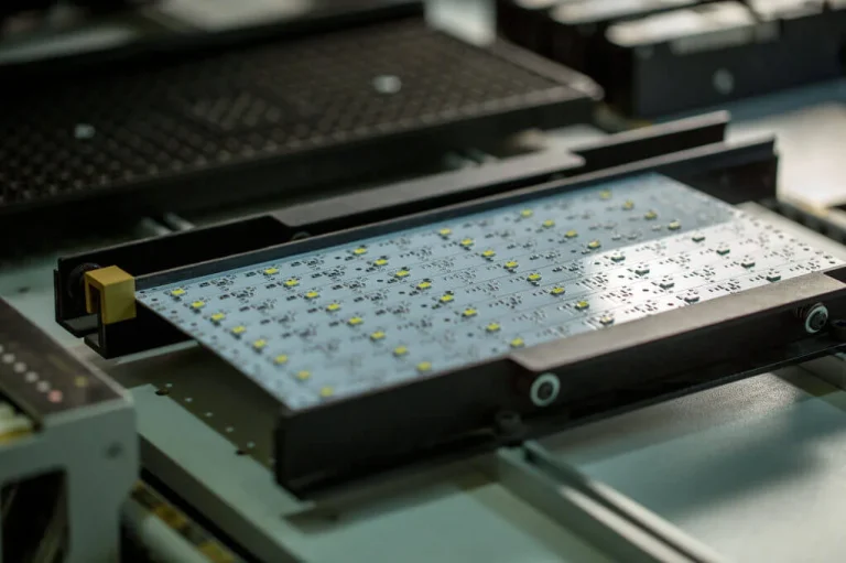
An LED PCB (LED Printed Circuit Board) is a specialized circuit board designed to electrically connect, mechanically support, and thermally manage LED components.
Its primary functions include:
- Providing electrical connections for LED components
- Distributing power to LED arrays
- Managing heat generated during operation
- Supporting LED drivers and control circuits
- Maintaining mechanical stability
- Integrating LEDs into compact lighting products
A conventional PCB may use FR-4 as its primary substrate, while an LED PCB may use aluminum, copper, ceramic, or flexible materials depending on the power level and application.
For low-power indicator applications, conventional FR-4 can be sufficient. For higher-power lighting systems, aluminum MCPCB, copper-core PCB, or ceramic PCB may provide better thermal performance.
In other words, the PCB is not simply the platform on which an LED is installed. It is also a critical part of the LED’s thermal path.
How Does an LED PCB Work?
The operating principle of an LED PCB involves both electrical conduction and thermal transfer.
When electrical power is supplied to the circuit, current flows through the copper traces to the LED components. Inside an LED semiconductor, electrons and holes recombine and release energy as photons, producing visible light.
However, not all electrical power is converted into light. A substantial portion becomes heat.
The resulting thermal path is typically:
LED Junction → LED Package → Solder Joint → Copper Circuit → Dielectric Layer → Metal Core → Heat Sink → Ambient Environment
The PCB therefore needs to provide a low-resistance thermal pathway.
If the generated heat cannot be removed efficiently, LED junction temperature can increase, potentially causing:
- Reduced luminous output
- Color shift
- Lower efficiency
- Accelerated component aging
- Shortened operating life
- Thermal damage
This is one of the fundamental differences between LED PCB design and conventional PCB design.
Key Components of an LED PCB
A typical LED printed circuit board contains several functional layers and components.
LED Chips or LED Packages
The LED is the light-generating component.
Common LED packages include various SMD configurations designed for different:
- Power levels
- Luminous flux
- Color temperatures
- Wavelengths
- Beam characteristics
PCB Substrate
The substrate provides structural support and establishes the thermal path.
Common choices include:
- Aluminum
- Copper
- Ceramic
- FR-4
- Polyimide for flexible LED PCBs
Copper Circuit Layer
Copper traces carry current between the power source, LEDs, drivers, and control components.
Copper thickness affects:
- Current-carrying capacity
- Electrical resistance
- Heat spreading
- Mechanical characteristics
Dielectric Layer
In an MCPCB, the dielectric layer electrically isolates the copper circuit from the metal base while maintaining an efficient thermal path.
Its thermal conductivity and thickness directly affect overall thermal resistance.
Thermal Management Structure
Depending on the design, an LED PCB may use:
- Thermal pads
- Thermal vias
- Copper heat-spreading areas
- Metal cores
- External heat sinks
- Thermal interface materials
Types of LED PCB Boards
Different applications require different PCB structures.
Aluminum LED PCB / MCPCB
Aluminum LED PCB, commonly called MCPCB (Metal Core Printed Circuit Board), is one of the most widely used LED PCB technologies.
Typical structure:
Copper Circuit Layer → Dielectric → Aluminum Base
Advantages include:
- Good thermal conductivity
- Lightweight construction
- Relatively low cost
- Good mechanical stability
- Suitable for high-power LED systems
Typical applications include:
- Streetlights
- Floodlights
- Automotive lighting
- Commercial lighting
- Industrial lighting
- LED signage
Copper Core LED PCB
Copper provides higher thermal conductivity than aluminum and can be used where the thermal load is particularly high.
Copper-core PCBs are often considered for:
- High-power LED arrays
- Automotive lighting
- High-density lighting systems
- Specialized industrial applications
The main disadvantage is higher material and manufacturing cost.
FR-4 LED PCB
FR-4 LED PCBs can be suitable for low-power LED applications where thermal requirements are relatively modest.
Typical examples include:
- Indicator LEDs
- Small display modules
- Low-power consumer electronics
- Simple control boards
FR-4 is economical and widely available, but its thermal conductivity is significantly lower than that of metal-core constructions.
Ceramic LED PCB
Ceramic substrates combine excellent thermal characteristics with strong electrical insulation.
They can be used in:
- High-reliability lighting
- High-power LED packages
- Harsh environments
- Specialized industrial applications
- Advanced medical and automotive systems
Flexible LED PCB
Flexible LED PCBs typically use polyimide or similar flexible substrates.
They are suitable for:
- Flexible LED strips
- Wearable products
- Curved lighting
- Automotive interior lighting
- Decorative lighting
- Compact consumer electronics
Their main advantage is their ability to conform to curved or irregular surfaces.
Hybrid LED PCB
A hybrid LED PCB combines different PCB technologies or substrate structures to meet specific electrical, thermal, and mechanical requirements.
These designs are useful when one material cannot meet all performance requirements.
LED PCB vs Standard PCB
| Feature | LED PCB | Standard PCB |
|---|---|---|
| Primary purpose | LED mounting, power distribution and thermal management | General electronic circuits |
| Common substrate | Aluminum, copper, ceramic, FR-4, flexible materials | Mainly FR-4 |
| Thermal management | Specifically optimized | Usually secondary consideration |
| Heat dissipation | High with MCPCB/ceramic construction | Generally limited |
| Typical application | LED lighting, automotive lighting, displays | Computing, control, communications |
| Design focus | Electrical + optical + thermal | Mainly electrical + mechanical |
| Cost | Generally higher for specialized structures | Generally lower |
The major difference is not simply the substrate. It is the level of thermal engineering built into the PCB structure.
Common Applications of LED PCBs
Automotive Lighting
Automotive applications include:
- Headlights
- Taillights
- Brake lights
- Daytime running lights
- Interior lighting
- Dashboard lighting
These applications require excellent resistance to vibration, thermal cycling, moisture, and electrical transients.
Commercial Lighting
LED PCBs are widely used in:
- Downlights
- Panel lights
- Streetlights
- Floodlights
- High-bay fixtures
- Linear lighting
Long operating periods make thermal reliability especially important.
Consumer Electronics
LED PCBs are used for:
- Display backlighting
- Camera flash modules
- Indicator lighting
- Portable devices
- Smart-home products
Medical Devices
LED lighting is used in:
- Surgical lighting
- Diagnostic equipment
- Medical displays
- Inspection systems
Medical applications place high demands on color consistency, stability, and reliability.
Industrial Lighting
Industrial facilities use LED PCBs for:
- High-bay lighting
- Machine indicators
- Inspection equipment
- Control panels
- Industrial display systems
Architectural Lighting
Flexible and compact LED PCB structures enable:
- Building illumination
- Decorative lighting
- Landscape lighting
- Signage
- Customized lighting effects
Advantages of LED PCB Technology
Superior Thermal Management
One of the biggest advantages of a dedicated LED PCB is the ability to transfer heat away from LED components efficiently.
This is especially important for high-power LEDs.
Long Operating Life
Proper thermal management can significantly improve LED reliability and reduce premature failures.
It is important to note that advertised LED lifetimes such as 50,000 or 100,000 hours depend on operating conditions, junction temperature, drive current, and product specifications. The PCB itself does not independently determine LED lifetime.
High Energy Efficiency
LED technology can provide high luminous efficacy compared with traditional lighting technologies, reducing energy consumption for many applications.
Compact Design
SMD LEDs allow large numbers of light sources to be placed in a relatively small area.
This supports:
- Slim lighting fixtures
- High-density arrays
- Compact electronics
- Customized shapes
Design Flexibility
LED PCBs can be manufactured in different shapes, layer structures, and materials to meet specific application requirements.
Strong Mechanical Reliability
Metal-core boards can provide structural rigidity in addition to thermal performance, which is useful for automotive and industrial lighting.
Understanding SMD LED PCB Technology
SMD LED PCB technology has become extremely common in modern lighting systems.
SMD LEDs are soldered directly onto the PCB surface rather than inserted through drilled holes.
This provides several benefits:
- High component density
- Automated assembly
- Compact design
- Consistent placement
- Reduced board size
- Compatibility with mass production
SMD LED PCB applications include:
- Smartphone flashes
- LED strips
- Automotive lighting
- LED displays
- Consumer lighting
- Commercial fixtures
For high-density lighting arrays, automated SMT assembly can achieve much higher placement consistency than manual assembly.
Thermal Management in LED PCB Design
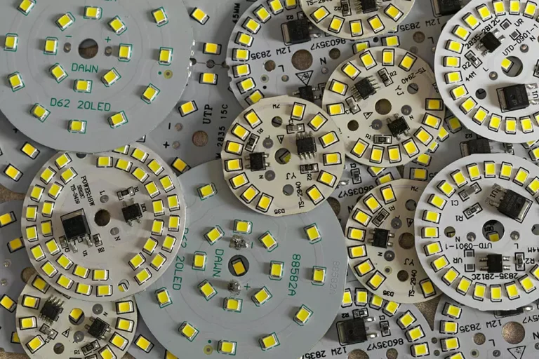
Thermal management is arguably the most important engineering consideration in high-power LED PCB design.
Why Heat Matters
As LED junction temperature increases, luminous performance and reliability can decline.
Possible effects include:
- Lower luminous flux
- Color variation
- Reduced efficiency
- Accelerated aging
- Shortened lifetime
Engineers therefore need to manage the complete thermal path rather than relying only on the LED package.
Thermal Design Techniques
Common approaches include:
Metal-Core Substrate
Aluminum or copper bases provide better heat transfer than standard FR-4.
Thermal Pads
Large thermal pads beneath power components provide a direct heat-transfer interface.
Thermal Vias
Thermal vias transfer heat from one copper layer to another.
Copper Heat Spreading
Larger copper areas can distribute heat across a wider surface area.
Heat Sinks
For higher-power applications, the PCB may be mechanically connected to an external heat sink.
Thermal Interface Materials
Thermal pads, grease, or other interface materials may be used between the PCB and heat sink to reduce interface resistance.
LED PCB Manufacturing Process
The general manufacturing process includes:
Engineering Review → Material Selection → PCB Fabrication → Solder Mask → Surface Finish → SMT Assembly → Reflow → Inspection → Functional Testing
For aluminum and copper-core PCBs, additional control is required during dielectric bonding and thermal-interface formation.
Design and Engineering
Engineers review:
- Electrical specifications
- LED package
- Power consumption
- PCB dimensions
- Thermal requirements
- Component placement
- Manufacturing constraints
PCB Fabrication
Depending on the board structure, the process can include:
- Imaging
- Etching
- Drilling
- Plating
- Lamination
- Surface finishing
LED Assembly
Components are mounted through SMT or THT processes.
Typical SMT workflow:
Solder Paste Printing → SPI → Pick-and-Place → Reflow → AOI → X-Ray if required
Testing
The completed assembly can undergo:
- Visual inspection
- AOI
- X-ray
- Electrical testing
- Functional testing
- Thermal testing
How to Choose the Right LED PCB
Selecting the appropriate board requires balancing technical requirements and cost.
1. Determine Power Requirements
Low-power indicators may work with FR-4, while high-power LEDs may require MCPCB or copper-core construction.
2. Analyze Thermal Requirements
Consider:
- LED power
- Ambient temperature
- Operating duration
- Enclosure design
- Airflow
- Heat-sink configuration
3. Evaluate Environmental Conditions
Consider whether the PCB will experience:
- High humidity
- Vibration
- Dust
- Chemicals
- UV exposure
- Extreme temperatures
4. Consider Board Geometry
Flexible PCBs may be appropriate for curved products, while rigid metal-core PCBs are typically better for high-power lighting.
5. Check Compliance Requirements
Depending on the market and application, requirements may include:
- RoHS
- UL
- CE
- ISO-based quality systems
- Automotive-specific requirements
How to Choose an LED PCB Manufacturer
A reliable LED PCB manufacturer should provide more than basic PCB fabrication.
Important evaluation criteria include:
Thermal Manufacturing Capability
Confirm that the manufacturer can produce:
- Aluminum MCPCB
- Copper-core PCB
- Ceramic PCB
- Flexible LED PCB
- Thermal vias
- High-current copper structures
SMT Assembly Capability
The manufacturer should have:
- Automatic pick-and-place machines
- SPI
- AOI
- X-ray
- Controlled reflow systems
- High-precision stencil capabilities
Engineering Support
A strong partner should perform:
- DFM review
- BOM review
- Component sourcing
- Thermal-design review
- Assembly review
- Production optimization
Quality Management
Look for:
- ISO 9001
- ISO 13485 when medical products are involved
- IATF 16949 for automotive applications
- IPC-based manufacturing controls
- Traceability systems
Why Choose Kingda for LED PCB Manufacturing and Assembly?
Kingda provides an integrated PCB manufacturing and PCBA assembly solution that covers PCB fabrication, component sourcing, SMT, THT, inspection, testing, and production support. This one-stop model can reduce the communication gaps that often arise when PCB fabrication and assembly are handled by separate suppliers.
Kingda’s published PCB manufacturing capabilities include aluminum PCB, copper-base PCB, FR-4, flexible PCB, rigid-flex PCB, HDI PCB, and high-frequency PCB, giving customers different material and construction options for LED and other specialized electronic applications.
For PCB assembly, Kingda states that its facilities support automated SMT production, SPI, AOI, X-ray inspection and functional testing. The company also supports miniature components and fine-pitch packages for complex electronic assemblies.
Its published quality certifications include ISO 9001, ISO 13485, IATF 16949, ISO 14001 and UL certification, supporting projects in industrial, medical, automotive and other reliability-sensitive sectors.
Kingda can also support the transition from PCB prototype to low-volume and mass production, helping engineering teams maintain production continuity as the product scales.
LED PCB Selection Checklist
Before placing an order, confirm the following:
Electrical
- LED operating voltage
- LED current
- Total power
- Driver requirements
- Dimming requirements
Thermal
- Substrate type
- Thermal conductivity
- Dielectric thickness
- Copper thickness
- Heat sink requirements
- Ambient temperature
Mechanical
- Board dimensions
- Thickness
- Mounting holes
- Flexibility
- Connector location
Manufacturing
- SMT/THT requirements
- Stencil design
- Surface finish
- Solder mask color
- AOI/X-ray requirements
- Functional testing
Compliance
- RoHS
- UL
- CE
- Automotive or medical requirements where applicable
Conclusion
So, what is an LED PCB?
An LED PCB is a specialized printed circuit board that combines electrical distribution, mechanical support, and thermal management to enable reliable LED operation.
Its performance depends on much more than simply mounting LEDs onto a board. Engineers must consider the substrate, dielectric layer, copper thickness, thermal path, solder mask, LED package, component placement, reflow profile, and final inspection strategy.
For low-power applications, FR-4 may provide a practical and economical solution. For higher-power lighting, aluminum MCPCB, copper-core PCB, or ceramic LED PCB can provide significantly better thermal performance. Flexible LED PCBs provide another option when the product requires curved or space-constrained installation.
With the increasing use of LED technology in automotive lighting, commercial lighting, consumer electronics, medical equipment, industrial systems, and smart lighting, selecting an experienced LED PCB manufacturer and assembly partner is becoming increasingly important.
Kingda’s one-stop PCB manufacturing and assembly capabilities provide a practical path from LED PCB design and prototyping to component sourcing, SMT assembly, testing, and volume production, helping customers develop reliable LED products while reducing manufacturing complexity.