The rapid development of compact, lightweight, and highly integrated electronic products has increased demand for Flex PCB Assembly. Unlike conventional rigid circuit boards, Flexible PCBs (FPCs) can bend, fold, and conform to complex mechanical structures, allowing engineers to integrate electronic circuits into spaces that would be difficult or impossible to reach with traditional rigid boards.
From smartphones and wearable devices to medical equipment, automotive electronics, aerospace systems, cameras, sensors, and industrial equipment, flexible PCB assembly provides an effective way to reduce wiring, save space, and improve system integration.
The real value of flex technology, however, is not simply flexibility. A successful Flex PCB Assembly process must also address material behavior, component placement, soldering, mechanical support, thermal management, inspection, and long-term reliability.
This article explores what Flex PCBs are, what Flex PCB Assembly means, the major types of flexible circuits, the assembly process, key advantages, applications, emerging technologies, and how Kingda supports flexible and rigid-flex PCB manufacturing and assembly.
What Are Flex PCBs?
A Flex PCB, also known as a Flexible Printed Circuit (FPC), is a circuit board designed to bend or flex while maintaining reliable electrical connections.
Unlike conventional rigid PCBs that typically use FR-4 as a structural substrate, flexible circuits commonly use thin flexible materials such as polyimide or other specialized flexible substrates.
A Flex PCB generally consists of:
- Flexible substrate
- Copper conductive layers
- Coverlay or solder mask
- Adhesive systems where applicable
- Surface finish
- Stiffeners where required
The flexibility of the circuit allows it to conform to curved, folded, or moving structures.
Key Characteristics of Flexible PCBs
Important characteristics of Flexible PCBs include:
- Bendability
- Reduced thickness
- Lower weight
- Three-dimensional routing capability
- Improved space utilization
- Reduced wiring and connector requirements
- Resistance to vibration and mechanical movement
- High design freedom
Because of these characteristics, flexible circuits are frequently used in products where space is limited or where electrical connections must move with mechanical components.
What Is Flex PCB Assembly?
Flex PCB Assembly is the process of mounting and soldering electronic components onto a flexible printed circuit.
Although the fundamental assembly principles are similar to rigid PCB assembly, flexible circuits require additional mechanical and process controls because the PCB substrate can move or deform during manufacturing.
A typical Flex PCB Assembly process may include:
Material Preparation → PCB Baking/Drying → Stencil Printing → Component Placement → Reflow Soldering → Inspection → Testing → Final Assembly
One of the most important differences is that a flexible circuit usually needs to be supported by a suitable carrier or fixture during solder paste printing and component placement.
Without adequate support, the flexible substrate can deform, causing problems such as:
- Solder paste misalignment
- Component placement errors
- Uneven board support
- Solder defects
- Dimensional instability
Therefore, successful flex assembly depends on both the PCB design and the manufacturing process.
Types of Flexible PCBs
Flexible circuits can generally be categorized according to the number of conductive layers and structural complexity.
Single-Sided Flex PCB
A single-sided flexible PCB contains one conductive copper layer.
It is generally the simplest and most economical flexible circuit structure.
Common applications include:
- LED circuits
- Simple sensors
- Membrane switches
- Simple interconnections
- Compact control circuits
The simple structure provides excellent flexibility and can be appropriate when the circuit does not require routing on both sides.
Double-Sided Flex PCB
A double-sided Flex PCB contains two conductive layers separated by an insulating flexible dielectric.
Compared with single-sided flex circuits, double-sided designs provide greater routing flexibility and can support more complex circuits.
Typical applications include:
- Camera modules
- Portable electronics
- Sensors
- Compact control modules
- Consumer electronics
Multilayer Flex PCB
Multilayer Flexible PCBs contain three or more conductive layers and provide significantly greater circuit density.
They are useful for applications requiring:
- Complex routing
- Higher circuit density
- Controlled impedance
- Shielding
- Multiple signal and power layers
Applications may include:
- Medical electronics
- Aerospace systems
- Advanced automotive electronics
- High-density consumer electronics
- Communication devices
The trade-off is that multilayer flex circuits generally have greater manufacturing complexity and may provide less flexibility than simpler single-layer constructions.
Rigid-Flex PCB
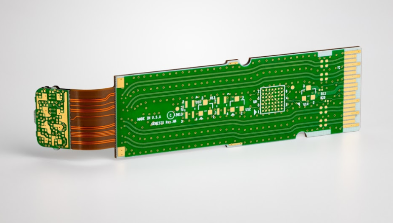
A Rigid-Flex PCB combines rigid PCB sections with flexible circuit sections in one integrated structure.
This allows engineers to combine:
- Mechanical rigidity
- Flexible routing
- Three-dimensional packaging
- Fewer connectors
- Reduced cable assemblies
Rigid-flex technology is particularly valuable when multiple PCB sections need to be connected within a compact mechanical assembly.
Flex PCB vs. Rigid PCB
| Feature | Flex PCB | Rigid PCB |
|---|---|---|
| Flexibility | High | Low |
| Weight | Low | Higher |
| Space Utilization | Excellent | Moderate |
| 3D Routing | Yes | Limited |
| Vibration Resistance | Very good for suitable designs | Application dependent |
| Connector Reduction | High potential | More limited |
| Design Complexity | Higher | Lower |
| Typical Cost | Higher | Lower |
| Best Applications | Compact, moving, curved systems | General electronics |
A Flex PCB is not necessarily a replacement for every rigid PCB. The correct solution depends on the mechanical structure, electrical requirements, expected flex cycles, thermal conditions, and manufacturing budget.
Advantages of Flex PCB Assembly
1. Space and Weight Reduction
One of the most important advantages of Flex PCB Assembly is its ability to save space and weight.
Flexible circuits can replace combinations of:
- Wires
- Cables
- Connectors
- Separate rigid boards
This can significantly simplify compact electronic assemblies.
2. Three-Dimensional Design Freedom
Unlike rigid PCBs, flexible circuits can be routed through three-dimensional structures.
This allows designers to place electronics around:
- Curved housings
- Hinges
- Moving mechanisms
- Narrow mechanical gaps
- Irregular product surfaces
3. Reduced Connectors and Interconnections
A flexible circuit can connect multiple electronic sections directly.
Reducing connectors and cable assemblies can reduce:
- Component count
- Assembly steps
- Potential connection failures
- Mechanical space requirements
4. Improved Vibration and Mechanical Performance
The flexible substrate can absorb certain levels of mechanical movement and vibration more effectively than rigid interconnect structures.
This makes Flex PCBs useful in automotive, aerospace, industrial, and other mechanically demanding environments.
5. High Integration
A flexible circuit can combine electrical interconnections with mechanical routing, enabling highly integrated product architectures.
6. Suitable for Dynamic Applications
Flexible circuits are especially useful when the circuit must repeatedly bend or move.
Examples include:
- Folding electronic devices
- Camera modules
- Moving sensor assemblies
- Hinged mechanisms
- Wearable electronics
However, dynamic-flex applications require careful control of bend radius, copper geometry, materials, and flex-cycle requirements.
Applications of Flex PCBs
Automotive Electronics
Flex PCBs are increasingly used in automotive applications because modern vehicles require more electronics within limited installation spaces.
Applications include:
- Automotive displays
- Lighting
- Sensors
- Camera modules
- Battery systems
- Steering-wheel electronics
- ADAS modules
- Instrument clusters
Flexible circuits can conform to vehicle structures and reduce the need for conventional wiring harnesses and connectors.
Kingda supports flexible PCB and rigid-flex PCB assembly for automotive and other high-reliability applications. Its published capabilities include rigid, flexible, rigid-flex, HDI, high-TG, high-frequency, and controlled-impedance PCB assembly.
Aerospace and Defense
Aerospace systems require lightweight, compact, and reliable electronic assemblies.
Flexible circuits can reduce wiring and provide greater packaging freedom in:
- Avionics
- Navigation systems
- Communication equipment
- Radar-related electronics
- Control systems
- Satellite electronics
The flexibility and lower weight of FPCs can be valuable where mechanical integration and weight reduction are priorities.
Medical Electronics
Flexible circuits are increasingly important in medical devices that require compact, lightweight, and ergonomically integrated electronics.
Applications include:
- Wearable medical monitors
- Diagnostic devices
- Imaging equipment
- Medical sensors
- Portable medical equipment
Medical applications may also require controlled materials, traceability, and specialized quality management.
Kingda reports ISO 13485 certification as part of its quality management system and provides PCB and PCBA manufacturing for medical applications.
Consumer Electronics
Consumer electronics have been a major driver of flexible circuit adoption.
Applications include:
- Smartphones
- Smartwatches
- Wearable devices
- Cameras
- Tablets
- Foldable devices
- Portable electronics
Flex circuits make it easier to integrate displays, cameras, sensors, buttons, batteries, and other modules into thin product architectures.
Industrial Electronics
Industrial systems may use flexible circuits in:
- Sensors
- Control modules
- Human-machine interfaces
- Measurement equipment
- Robotics
- Industrial cameras
Flexible interconnects can simplify installation where conventional wiring is difficult.
Flex PCB Assembly Process
1. Material Preparation
The first step is preparing the flexible PCB and assembly materials.
Typical materials and equipment include:
- Flex PCB
- Components
- Solder paste
- Stencils
- Carrier fixtures
- Assembly equipment
- Inspection systems
Material handling should prevent contamination, mechanical damage, and unnecessary deformation of the flexible circuit.
2. Flex PCB Baking and Moisture Control
Depending on the materials and storage conditions, flexible substrates may require controlled drying or baking before assembly.
Moisture management is important because absorbed moisture can affect soldering and may increase the risk of defects during thermal processing.
Baking temperature and duration should follow the PCB manufacturer’s material specifications rather than using one universal setting.
3. Carrier and Fixture Setup
Because a flexible PCB is not mechanically rigid, it typically requires a support fixture or carrier during SMT assembly.
The carrier helps maintain:
- Flatness
- Dimensional stability
- Component-placement accuracy
- Stencil alignment
Proper carrier design is especially important for thin or complex flexible circuits.
4. Solder Paste Printing
Solder paste is deposited onto the PCB pads using a stencil.
For flexible circuits, stencil printing requires careful control because excessive mechanical pressure can deform the substrate.
Important factors include:
- Stencil design
- Solder paste volume
- Squeegee pressure
- Board support
- Alignment accuracy
- Paste condition
5. Component Placement
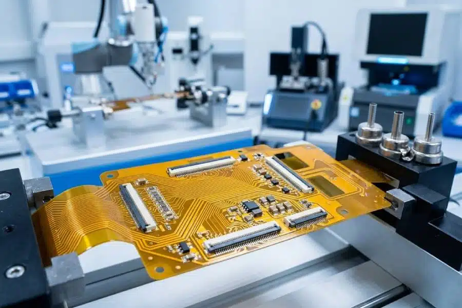
Automated pick-and-place equipment positions components onto the flex PCB.
For fine-pitch components, accurate fiducials and stable carrier support are particularly important.
Kingda supports fine-pitch SMT assembly and BGA/QFN-related packages as part of its broader PCB assembly capability.
6. Reflow Soldering
After component placement, the assembly moves through a controlled reflow process.
The temperature profile must be developed based on:
- PCB material
- Component specifications
- Solder paste
- Copper distribution
- Flexible substrate properties
The objective is to achieve reliable solder joints without damaging the flexible substrate or components.
7. Inspection
After reflow, the assembled PCB is inspected.
Depending on the application, inspection may include:
- SPI
- AOI
- X-ray inspection
- Visual inspection
AOI can identify component-placement and visible soldering defects, while X-ray inspection can evaluate hidden solder joints such as BGA connections.
8. Electrical and Functional Testing
The final stage verifies that the assembled Flex PCB performs according to its requirements.
Testing may include:
- Continuity testing
- Insulation testing
- ICT
- Functional testing
- Programming
- System-level verification
The exact test strategy depends on the product and application.
Key Design Considerations for Flex PCB Assembly
Successful Flex PCB Assembly begins with a manufacturable PCB design.
Bend Radius
The bend radius is one of the most important parameters for flexible circuits.
The appropriate minimum bend radius depends on factors such as:
- Number of copper layers
- Copper thickness
- Flexible material
- Dynamic vs. static flexing
- Expected flex cycles
Dynamic-flex applications normally require more conservative mechanical design than boards that are bent only during final installation.
Copper Selection
Copper thickness affects:
- Electrical current capacity
- Flexibility
- Mechanical fatigue
- Manufacturing cost
Thinner copper may provide greater flexibility, while thicker copper can improve current-carrying capability.
The correct balance depends on the application.
Component Placement
Components should generally be positioned away from areas intended for repeated bending.
Rigidized or stiffened sections can be used around component areas when necessary.
Stiffeners
Flex PCB stiffeners can be added beneath connectors or component areas to provide greater mechanical support.
Common stiffener materials include:
- FR-4
- Polyimide
- Stainless steel
The appropriate material depends on the mechanical and assembly requirements.
Keep-Out Areas
Designers should define areas where components, vias, or copper structures should not interfere with intended bending zones.
Controlled Impedance
High-speed Flex PCBs require careful control of:
- Dielectric thickness
- Trace width
- Copper thickness
- Material dielectric properties
- Reference planes
For high-speed applications, the flex design should be reviewed together with the manufacturer before production.
Emerging Flex PCB Technologies
Advanced Flexible Materials
Traditional polyimide remains widely used, but advanced materials such as Liquid Crystal Polymer (LCP) are increasingly considered for specialized applications requiring low moisture absorption, high-frequency performance, and dimensional stability.
Material selection should be based on the actual electrical, thermal, chemical, and mechanical requirements of the application.
High-Density Flex PCB
As electronic devices become smaller, flexible circuits increasingly incorporate:
- Fine-line routing
- Microvias
- HDI structures
- Fine-pitch components
- High-density multilayer designs
These technologies allow more functions to be integrated into smaller spaces.
Rigid-Flex Integration
Rigid-flex PCB technology continues to grow because it allows designers to combine multiple rigid circuit sections with flexible interconnections into a single assembly.
This can reduce:
- Cable count
- Connectors
- Assembly operations
- Mechanical interfaces
Flexible Electronics for Wearables and Medical Devices
Wearable electronics and medical devices are driving demand for thinner and more conformable flexible circuits.
Future designs may increasingly combine flexible PCBs with:
- Sensors
- Wireless communication
- Battery systems
- Miniature processors
- Flexible displays
- Physiological monitoring components
How Kingda Supports Flex PCB Assembly
For customers looking for a reliable Flex PCB Assembly manufacturer, manufacturing capability needs to cover more than simply component soldering.
Kingda provides integrated flexible PCB fabrication and assembly, supporting customers through PCB manufacturing, component sourcing, SMT/THT assembly, inspection, testing, and production. Kingda specifically lists Flexible PCB Assembly and Rigid-Flex PCB Assembly among its PCB assembly capabilities.
One-Stop Flex PCB Manufacturing and Assembly
Kingda integrates:
Flex PCB Fabrication → Component Sourcing → SMT/THT Assembly → Inspection → Testing → Final Assembly
This helps customers manage multiple stages of flexible electronics manufacturing through one supplier.
Flex and Rigid-Flex PCB Capability
Kingda’s published PCB capabilities include Flex PCB, Rigid-Flex PCB, HDI PCB, multilayer PCB, high-frequency PCB, high-TG PCB, heavy copper PCB, and controlled-impedance PCB assembly.
This allows customers to select flexible circuit structures according to their electrical, mechanical, thermal, and application requirements.
Prototype to Mass Production
Kingda supports prototype, low-volume, and mass-production PCB assembly, allowing customers to move from early flexible PCB prototypes toward larger production quantities without necessarily changing manufacturing partners.
Its published rapid prototyping service also supports rapid PCBA prototyping, including flex and rigid-flex PCBs.
DFM and DFA Engineering Support
Flex circuits can be significantly more sensitive to mechanical and assembly constraints than rigid PCBs.
Kingda provides engineering services including:
- DFM review
- DFA analysis
- Gerber review
- BOM verification
- Pick-and-place verification
- Component availability analysis
- Alternative component recommendations
- Prototype support
- Production process optimization
These engineering services can help identify design issues before production and reduce unnecessary revisions.
Comprehensive Inspection and Testing
Kingda’s published capabilities include SPI, AOI, X-ray, ICT, FCT, and first-article inspection, allowing inspection and testing to be matched to the requirements of the flexible PCB assembly.
For flex assemblies using BGA or other hidden solder joints, X-ray inspection can provide additional verification beyond optical inspection.
Quality Management
Kingda reports IATF 16949, ISO 13485, and ISO 9001 quality management certifications. These systems support manufacturing requirements across automotive, medical, industrial, and other demanding electronics applications.
Why Choose Kingda for Flex PCB Assembly?
When evaluating a Flex PCB Assembly manufacturer, consider the complete manufacturing capability rather than assembly price alone.
Kingda provides:
- Flex PCB manufacturing
- Rigid-Flex PCB manufacturing
- Flex PCB assembly
- Rigid-Flex PCB assembly
- SMT and THT assembly
- Component sourcing
- DFM/DFA support
- Prototype manufacturing
- Low-volume production
- Volume production
- AOI and X-ray inspection
- ICT and functional testing
- One-stop PCB and PCBA manufacturing
This integrated approach can help simplify supply-chain management and improve communication between PCB fabrication, component procurement, assembly, and quality-control teams.
Future Outlook for Flex PCB Assembly
The future of Flex PCB Assembly is closely connected to the continued miniaturization and integration of electronic products.
Several trends are likely to continue influencing the industry:
Greater Miniaturization
As products become thinner and more compact, flexible circuits can provide routing solutions that conventional rigid boards cannot.
More Rigid-Flex Integration
Rigid-flex technology can eliminate cables and connectors while simplifying three-dimensional electronics packaging.
Higher Circuit Density
Fine-line routing, microvias, and high-density interconnect technologies will enable more functionality within smaller flexible circuits.
More Wearable and Medical Electronics
Flexible circuits are well suited for products that must conform to irregular surfaces or move with the user.
Advanced Automotive Electronics
The growth of EVs, ADAS, sensors, displays, and vehicle connectivity will continue to create opportunities for flexible and rigid-flex PCB technologies.
High-Speed Flexible Electronics
As flexible circuits are increasingly used in high-speed systems, manufacturers will need to improve controlled impedance, low-loss materials, signal integrity, and high-density assembly.
Conclusion
Flex PCB Assembly is an important technology for modern electronics because it provides a combination of flexibility, compactness, low weight, high integration, and three-dimensional design freedom.
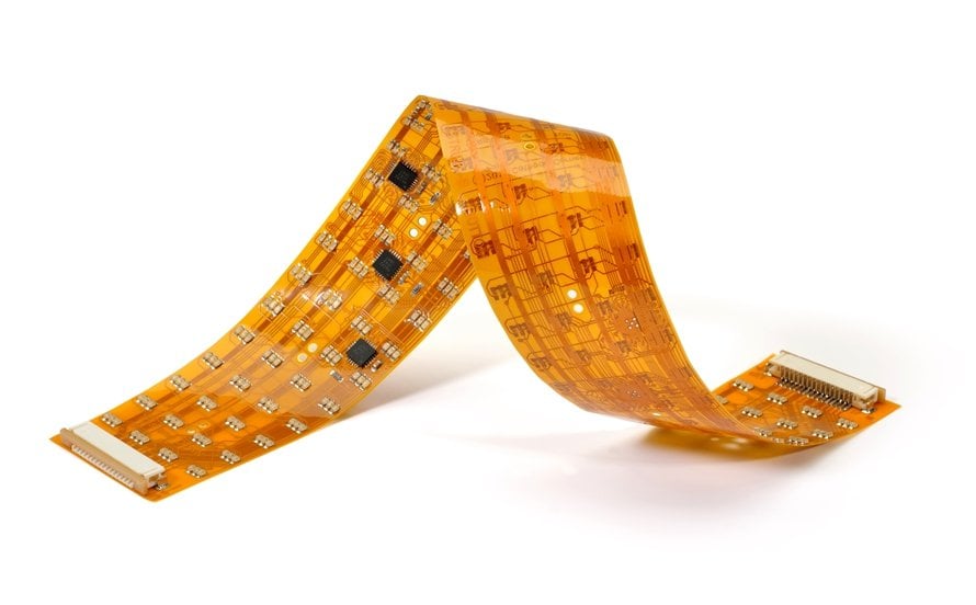
From smartphones and wearables to automotive electronics, aerospace systems, medical equipment, and industrial products, flexible circuits can simplify interconnections and enable product designs that are difficult to achieve with conventional rigid PCBs.
However, reliable flexible electronics require more than flexible materials. Material selection, Flex PCB Assembly is an impo, stiffener design, component placement, carrier support, soldering, inspection, testing, and manufacturability must all be considered.
For companies looking for an experiencedFlex PCB Assembly is an impo Kingda provides integrated flexible and rigid-flex PCB fabrication and assembly services, together with SMT/THT assembly, component sourcing, engineering support, inspection, testing, and production scalability.
From Flex PCB prototypes to low-volume and mass production, Kingda can provide a one-stop manufacturing solution for customers developing compact, lightweight, and high-reliability electronic products.