Single-Layer vs. Double-Sided vs. Multilayer FPC: Key Differences
What Is an FPC?
An FPC (Flexible Printed Circuit), also known as a flex PCB or flexible circuit, is a type of printed circuit board manufactured on a flexible insulating substrate.
Unlike conventional rigid PCBs, FPCs are thin, lightweight, and capable of bending and folding. Depending on the material and construction, they can also be designed for repeated dynamic flexing. This flexibility allows FPCs to follow complex three-dimensional mechanical layouts while integrating electrical interconnection and component mounting into a compact structure.
As smartphones, laptops, wearable devices, automotive electronics, and consumer drones become smaller and more integrated, demand for thinner, lighter, and higher-density flexible circuits continues to grow.
Like rigid PCBs, FPCs can be manufactured with different numbers of conductive layers. The three common configurations are single-layer, double-sided, and multilayer FPCs.
1. Single-Layer FPC
A Single-Layer FPC is the simplest type of flexible circuit. It has one conductive copper layer formed on a flexible insulating substrate.
Structure and Manufacturing
A typical single-layer FPC consists of:
- Flexible substrate
- Copper foil
- Adhesive, depending on construction
- Coverlay or protective coating
Polyimide (PI) is widely used as the substrate because of its flexibility, thermal stability, and electrical properties. Other materials, such as PET, can also be used for applications with different performance requirements.
During manufacturing, the copper foil is patterned through processes such as photoimaging and chemical etching. The resulting copper pattern forms the circuit traces and pads.
A coverlay is then applied to protect the copper traces, with openings created where solder pads or other exposed conductive areas are required. Depending on the application, exposed pads may receive a surface finish such as gold or tin to improve solderability and protect the copper surface.
The completed panel can then be routed, die-cut, or otherwise processed into individual FPCs.
Typical Applications
Because of its relatively simple structure and good flexibility, single-layer FPCs are commonly used where circuit routing requirements are limited.
Typical applications include:
- Industrial control equipment
- Electronic instruments
- Sensors
- Simple internal interconnections
- Compact electronic devices
For applications requiring the highest flexibility with relatively simple routing, a single-layer structure can be an efficient solution.
2. Double-Sided FPC
A Double-Sided FPC has conductive copper patterns on both sides of the flexible insulating substrate. This provides more routing space within the same overall footprint and is useful when a single copper layer cannot accommodate the required circuit layout.
Structure and Vias
The key difference between single-layer and double-sided FPCs is the presence of conductive structures that can electrically connect the two copper layers.
Plated through-holes or vias are commonly used to create electrical connections between the top and bottom copper layers. The basic process includes drilling the required holes, cleaning and preparing the hole walls, followed by copper plating to form the conductive connection.
The copper layers are then patterned to create the required traces and pads. Coverlay or another protective layer can be applied to both sides to protect the conductors and provide openings for component mounting or electrical connections.
Compared with a single-layer design, the additional copper layer provides greater routing flexibility and allows designers to create more compact interconnections.
Typical Applications
Double-sided FPCs are widely used in compact electronic products where space is limited but circuit density is higher.
Common applications include:
- Smartphones
- Automotive instrument panels
- Automotive lighting
- Display interconnections
- Internal device cables
- Electronic modules
For example, an automotive tail-light circuit may use a double-sided FPC to accommodate multiple electrical connections within a limited installation area.
3. Multilayer FPC
A Multilayer FPC contains three or more conductive layers separated by flexible insulating materials. Multiple flexible circuit layers are laminated together, while plated through-holes or other interconnection structures provide electrical connections between layers.
Structure and Interlayer Connections
Multilayer FPCs are designed for applications requiring significantly higher circuit density than single-layer or double-sided structures.
During manufacturing, individual circuit layers are patterned and laminated into a multilayer structure. Drilling and copper plating can create metallized holes that connect different conductive layers.
This allows electrical signals to transition between layers without requiring separate wire connections or extensive soldering. As a result, complex circuits can be integrated into a compact flexible assembly.
However, adding more layers also increases manufacturing complexity and can affect the overall flexibility of the circuit. The final mechanical performance depends on factors such as layer count, copper thickness, substrate material, coverlay construction, and the areas that are bonded together.
Flexible Multilayer FPC
For applications that require both high circuit density and significant flexibility, a flexible multilayer construction can provide a practical compromise.
In some designs, multiple flexible circuit layers are bonded together at selected regions while other areas remain less constrained. Keeping certain sections unbonded reduces mechanical restriction and allows the FPC to bend more easily.
A thin polyimide coating or other flexible protective layer may also be used instead of a relatively thick laminated cover structure in areas where improved flexibility is required.
This type of construction is particularly useful when an FPC must route through a three-dimensional space while carrying a relatively large number of electrical connections.
Typical Applications
Multilayer FPCs are commonly found in high-density electronic products, including:
- Smartphones
- Tablets
- Wearable electronics
- Advanced consumer electronics
- Compact electronic modules
- High-density interconnection systems
A multilayer FPC used as a smartphone flex cable, for example, can integrate numerous signal and power connections into a thin, space-efficient structure.
Single-Layer vs. Double-Sided vs. Multilayer FPC
The main differences between the three FPC structures can be summarized as follows:
| Feature | Single-Layer FPC | Double-Sided FPC | Multilayer FPC |
|---|---|---|---|
| Conductive layers | 1 | 2 | 3 or more |
| Routing density | Low | Medium | High |
| Circuit complexity | Low | Medium | High |
| Interlayer connection | Generally not required | Vias/plated holes commonly used | Vias/plated holes commonly used |
| Flexibility | Generally highest | High | Depends on construction |
| Manufacturing complexity | Low | Medium | High |
| Typical applications | Simple circuits | Compact electronic products | High-density electronics |
There is no universally best FPC structure. The appropriate configuration depends on circuit complexity, available space, mechanical movement, electrical requirements, and manufacturing cost.
How to Choose the Right FPC Structure
Choose a Single-Layer FPC for Simple Circuits
A single-layer structure is suitable when the circuit requires relatively few traces and maximum flexibility is important. It can also simplify manufacturing and reduce material usage.
Choose a Double-Sided FPC for Higher Routing Density
When a single copper layer cannot provide enough routing space, a double-sided FPC can increase circuit density without significantly increasing the footprint.
Choose a Multilayer FPC for Complex Circuits
Multilayer construction is appropriate when a design requires numerous electrical connections, high routing density, or compact integration.
For demanding applications, designers should evaluate not only the number of layers but also the bend areas, copper thickness, via configuration, coverlay, stiffeners, and connector regions.
Key Considerations in Flexible PCB Manufacturing
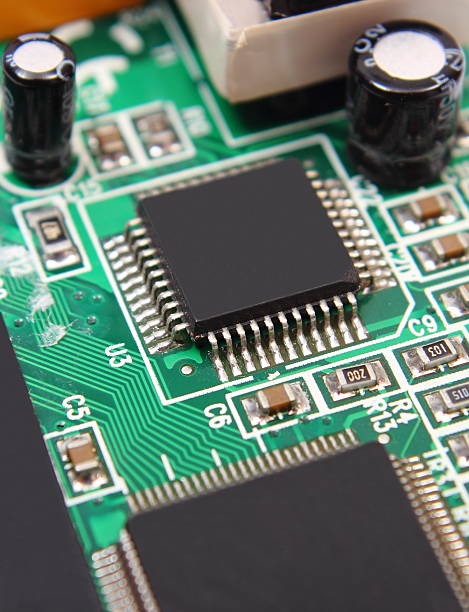
Successful Flexible PCB Manufacturing requires more than simply reducing the thickness of a rigid PCB. Electrical, mechanical, and manufacturing requirements must be considered together.
1. Substrate Material
Polyimide is widely used for demanding flexible circuits, while other flexible materials may be selected for specific cost or performance requirements.
2. Copper Type and Thickness
Copper thickness affects current-carrying capability, signal performance, mechanical flexibility, and manufacturability. For circuits designed for repeated bending, copper selection is particularly important.
3. Bend Radius
The minimum bend radius should be considered during PCB layout. Sharp bends can increase mechanical stress on copper traces and reduce the service life of a flex circuit.
4. Coverlay and Stiffeners
Coverlay protects exposed copper traces, while stiffeners may be added around connectors, component areas, or other regions requiring additional mechanical support.
5. Vias and Interlayer Connections
For double-sided and multilayer FPCs, via design must account for both electrical requirements and mechanical reliability. Poorly positioned or excessively concentrated vias can affect the flexibility of the circuit.
6. Surface Finish
Connector and soldering areas may require different surface finishes depending on the application. The selected finish should provide the required solderability, contact reliability, and corrosion resistance.
For a complete production strategy, it is important to consider PCB fabrication and assembly together. GOPCBA PCB Manufacturing and GOPCBA Flex PCB Assembly can help integrate fabrication and assembly requirements into the overall design process.
FPC Structure and Application: A Quick Guide
In general:
- Single-layer FPC: Best suited for simple circuits and applications where flexibility is a priority.
- Double-sided FPC: Suitable for higher routing density and compact interconnections.
- Multilayer FPC: Designed for complex, high-density circuits requiring extensive electrical interconnection.
- Flexible multilayer FPC: Useful when high circuit density must be combined with controlled bending or folding.
The choice should be made according to the actual electrical, mechanical, dimensional, and manufacturing requirements rather than simply selecting the highest possible layer count.
For projects that require prototype development before volume production, GOPCBA Prototype PCB Assembly can also be incorporated into the product development process.
Conclusion
FPC technology enables electronic designers to combine electrical interconnection with mechanical flexibility, making it especially valuable for compact and highly integrated products.
Single-layer FPCs offer a simple structure and excellent flexibility for relatively straightforward circuits. Double-sided FPCs provide additional routing capacity within a compact footprint, while multilayer FPCs support much higher circuit density and more complex interconnections.
As electronic products continue to become smaller and more integrated, selecting the appropriate FPC structure is increasingly important. The right combination of layer count, substrate, copper thickness, coverlay, vias, bend radius, and assembly requirements can improve both product performance and manufacturing reliability.
For complete PCB development and production support, GOPCBA PCB Design & Layout can be combined with flexible PCB fabrication and assembly services to optimize the design from layout through production.