As electronic products become smaller, lighter, and more highly integrated, conventional rigid and flexible circuit boards are increasingly being combined to meet complex design requirements. This has led to the rapid development of rigid-flex PCB technology.
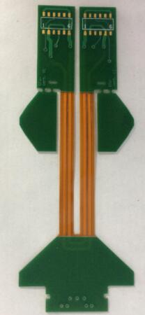
A rigid-flex PCB combines the mechanical strength of a rigid PCB with the flexibility of a flexible PCB (FPC). By integrating rigid and flexible sections into a single circuit structure, rigid-flex boards can reduce connectors, save internal space, simplify assembly, and improve overall system reliability.
Kingda provides professional PCB manufacturing capabilities for a wide range of applications, including multilayer PCBs, high-Tg PCBs, thick copper PCBs, flexible PCBs, rigid-flex PCB, high-frequency PCBs, metal-core PCBs, HDI PCBs, mixed-material laminates, and halogen-free PCBs.
What Is a Rigid-Flex PCB?
A rigid-flex circuit board is a hybrid PCB that combines rigid board sections with flexible circuit sections within one integrated construction.
A conventional rigid PCB provides mechanical support and stable component mounting, while an FPC provides flexibility and allows the circuit to bend or fold.
By combining these two technologies, a rigid-flex board can be designed with:
- Rigid areas for component mounting
- Flexible areas for bending and folding
- Integrated electrical interconnections
- Reduced connector requirements
- Improved space utilization
This structure is particularly useful when electronic components must be installed in limited or irregular spaces.
Why Rigid-Flex PCB Technology Is Important
Traditional electronic assemblies often require separate rigid PCBs and flexible cables connected through connectors.
Although this approach is relatively simple, it can increase the number of components, assembly steps, and potential failure points.
A rigid-flex PCB integrates these structures into a single board.
This can provide several advantages:
- Reduced assembly complexity
- Fewer connectors and cable assemblies
- Lower overall package volume
- Better use of internal product space
- Improved mechanical reliability
- Reduced risk of connection failures
- Greater design flexibility
For compact electronic products, eliminating unnecessary connectors can be especially valuable because connectors and cables occupy significant space.
Rigid-Flex PCB Manufacturing Process
Because a rigid-flex PCB combines rigid and flexible circuit structures, its manufacturing process is more complicated than that of a conventional rigid PCB or FPC.
The process generally includes circuit design, material preparation, flexible-circuit fabrication, rigid-layer fabrication, lamination, drilling, plating, surface finishing, electrical testing, and final inspection.
The exact process varies depending on the layer structure and product requirements.
1. PCB Design and Engineering Review
The process begins with an engineering design based on the customer’s electrical and mechanical requirements.
Engineers must define:
- Layer count
- Rigid and flexible areas
- Bend locations
- Minimum bend radius
- Copper thickness
- Dielectric materials
- Via structures
- Impedance requirements
- Component placement
- Board outline
Special attention must be given to the transition between rigid and flexible sections.
Poorly designed transition areas can create mechanical stress and reduce the long-term reliability of the circuit.
2. CAM Data Preparation
After the design is completed, engineering and CAM teams review the manufacturing data.
The CAM process typically includes:
- Gerber or ODB++ data verification
- Layer analysis
- Design-rule checking
- Drill-data review
- Stack-up verification
- Manufacturing compensation
- Panelization
- Production-tool preparation
For complex rigid-flex PCB manufacturing, engineering review is particularly important because the rigid and flexible materials may have different mechanical and thermal characteristics.
3. Flexible Circuit Fabrication
The flexible section is manufactured using materials designed to withstand repeated bending.
Polyimide is commonly used as the flexible dielectric because of its flexibility, thermal stability, and electrical performance.
The flexible circuit may undergo processes such as:
- Material preparation
- Copper pattern formation
- Etching or semi-additive processing
- Coverlay application
- Drilling or laser processing
- Plating
- Surface finishing
- Electrical testing
The flexible area must be protected during subsequent manufacturing operations to prevent damage.
4. Rigid PCB Fabrication
The rigid sections are manufactured using conventional PCB materials and processes.
Depending on the application, the rigid portion may contain multiple signal layers, power planes, ground planes, blind vias, buried vias, or HDI structures.
The rigid section provides mechanical support for components and helps maintain dimensional stability.
5. Lamination and Layer Integration
Lamination is one of the most critical stages of rigid-flex PCB manufacturing.
The rigid and flexible sections must be integrated according to the specified stack-up.
Because different materials can have different coefficients of thermal expansion (CTE), lamination parameters must be carefully controlled.
Important process parameters include:
- Temperature
- Pressure
- Heating rate
- Pressing time
- Material thickness
- Resin flow
- Alignment accuracy
Incorrect lamination conditions can result in delamination, dimensional deformation, resin-related defects, or reliability problems.
6. Drilling and Interconnection
Drilling creates the holes required for electrical interconnection.
Depending on the design, the PCB may use:
- Through holes
- Blind vias
- Buried vias
- Microvias
- Laser-drilled vias
For high-density designs, microvias and laser drilling can provide greater routing flexibility.
The drilling process must maintain high positional accuracy because registration errors can affect multilayer connectivity.
7. Copper Plating and Surface Finishing
After drilling, exposed hole walls are metallized to create reliable electrical connections between copper layers.
The PCB may then undergo copper electroplating and pattern plating according to the manufacturing process.
Surface finishing is applied to protect exposed copper and improve solderability.
Common surface finishes include:
- ENIG
- HASL
- OSP
- Immersion tin
- Immersion silver
The appropriate surface finish depends on the application, assembly process, reliability requirements, and component technology.
8. Inspection and Electrical Testing
Because rigid-flex boards are relatively complex and can have higher manufacturing costs, comprehensive inspection is essential.
Typical inspection procedures include:
- Automated optical inspection (AOI)
- Electrical continuity testing
- Insulation testing
- Dimensional inspection
- Microsection analysis
- Solderability testing
- Impedance testing when required
- Visual inspection
For high-reliability applications, additional mechanical and environmental testing may also be required.
Advantages of Rigid-Flex PCBs
The biggest advantage of a rigid-flex PCB is its ability to combine mechanical flexibility with rigid component-support areas.
Space Saving
Rigid-flex boards can replace separate rigid PCBs, flexible cables, and connectors.
This helps reduce the internal volume of electronic products.
Improved Reliability
Fewer connectors and cable interfaces mean fewer potential electrical and mechanical failure points.
This can improve the reliability of the complete electronic assembly.
Reduced Assembly Complexity
A single integrated board can replace multiple interconnected PCB assemblies.
This can reduce assembly operations and simplify production.
Improved Mechanical Design
Flexible sections can be folded or bent to follow the mechanical structure of the final product.
This is particularly useful for compact and irregularly shaped electronic devices.
Better Signal Integrity
Reducing connectors and cable transitions can help simplify signal paths.
For high-speed applications, careful stack-up and impedance control can further improve signal integrity.
Challenges of Rigid-Flex PCB Manufacturing
Although rigid-flex technology provides significant benefits, it also presents greater manufacturing challenges.
Compared with a conventional flexible PCB or rigid PCB, rigid-flex boards generally require more complex materials, processes, and engineering controls.
Major challenges include:
- Complex material combinations
- Higher manufacturing costs
- More complicated lamination
- Registration accuracy requirements
- Flexible-to-rigid transition reliability
- Controlled bend radius
- Higher inspection requirements
- More demanding process control
Because of these factors, the manufacturing yield of complex rigid-flex boards may be lower than that of standard PCBs.
Therefore, close cooperation between the PCB designer and manufacturer is important.
Design Considerations for Rigid-Flex PCBs
Successful rigid-flex PCB manufacturing begins with a design optimized for manufacturing.
Bend Radius
The bend radius should be selected according to the flexible material, copper thickness, layer count, and bending frequency.
Repeated bending requires more conservative mechanical design than a one-time assembly bend.
Copper Pattern
Copper traces should be routed carefully through flexible areas.
Sharp corners and abrupt changes in trace geometry can concentrate mechanical stress.
Rounded routing and appropriate spacing can improve flexibility and reliability.
Component Placement
Components should generally be positioned in rigid areas whenever possible.
Placing components directly within frequently bent sections can increase mechanical stress and reduce reliability.
Transition Area
The transition between rigid and flexible sections is particularly important.
Engineers should avoid creating concentrated mechanical stress near this region and should ensure adequate material support and routing clearance.
Applications of Rigid-Flex PCBs
Rigid-flex circuit boards are widely used in applications where space, weight, reliability, and mechanical flexibility are important.
Typical applications include:
- Automotive electronics
- Medical devices
- Communication equipment
- Industrial control systems
- Consumer electronics
- Instrumentation
- Aerospace electronics
- Defense electronics
- Power electronics
- Portable electronic devices
In automotive applications, rigid-flex boards can be used in control modules, sensors, displays, and compact electronic assemblies.
In medical equipment, their compact structure and high reliability make them suitable for portable and space-constrained devices.
In aerospace and other high-reliability applications, rigid-flex technology can help reduce connectors and wiring while improving system integration.
Rigid-Flex PCB vs. Conventional PCB
A conventional rigid PCB is optimized for mechanical stability and component mounting, while a flexible PCB is designed primarily for bending and space-constrained connections.
A rigid-flex PCB combines both functions.
| Feature | Rigid PCB | Flexible PCB | Rigid-Flex PCB |
|---|---|---|---|
| Mechanical flexibility | Low | High | High in flexible sections |
| Component mounting | Excellent | Limited | Excellent in rigid sections |
| Space utilization | Moderate | Excellent | Excellent |
| Connector reduction | Limited | Good | Excellent |
| Manufacturing complexity | Lower | Moderate | Higher |
| Typical cost | Lower | Moderate | Higher |
The best solution depends on the mechanical structure, electrical requirements, production volume, and reliability targets of the final product.
Kingda’s PCB Manufacturing Capabilities
For complex PCB projects, selecting an experienced manufacturing partner is essential.
Kingda supports a broad range of PCB technologies, including multilayer boards, HDI PCBs, high-frequency PCBs, flexible circuits, rigid-flex boards, thick copper boards, high-Tg PCBs, metal-core PCBs, and other customized PCB solutions.
Professional engineering support is particularly important for rigid-flex projects because material selection, stack-up design, bend requirements, lamination, drilling, plating, and inspection must work together as an integrated manufacturing system.
Conclusion
The development of compact and highly integrated electronic products is driving increasing demand for rigid-flex PCB technology.
By combining the structural strength of a rigid PCB with the flexibility of an FPC, rigid-flex boards can reduce connectors, save space, simplify assembly, and improve overall system integration.
However, rigid-flex PCB manufacturing requires stricter control of materials, lamination, registration, drilling, plating, flexible transition areas, and final inspection.
For demanding applications in automotive electronics, medical devices, communications, industrial controls, aerospace, and consumer electronics, choosing an experienced PCB manufacturer and involving the manufacturer early in the design process can significantly improve manufacturability and product reliability.