Flexible PCB vs Rigid PCB: How to Choose
The choice between a flexible PCB and a rigid board is usually decided by the mechanical envelope rather than by electrical performance. If the electronics have to fold into a space that a flat board cannot reach, or bend during assembly, then a flex circuit is the only way to make the product work. If they do not, a rigid board will be cheaper, easier to assemble and easier to test.
What a Rigid Board Gives You
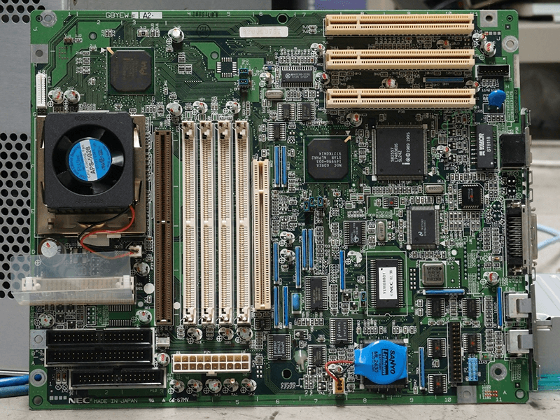
A rigid PCB is built on a stiff laminate, normally an epoxy glass composite, and it holds its shape once fabricated. Components mount on a flat, dimensionally stable surface, which is what makes high speed reflow assembly, fine pitch placement and automated optical inspection practical. The board can also carry heavy copper, large connectors and the mass of a heat sink without deforming.
The economics are mature. Rigid panels are produced on standardised lines, the materials are widely available and inexpensive, and a design can be moved between fabricators with little risk. Thermal management is easier too, because heat can be spread laterally through copper and conducted into a spreader or into the chassis through mounting hardware.
What Changes With a Flexible PCB
A flexible PCB uses a thin polymer film as its base rather than a rigid laminate. Polyimide is the usual choice because it survives soldering temperatures and has good dielectric behaviour, while polyester appears in low cost, low temperature applications. The result is a circuit that can be bent, folded or rolled, and that can be shaped to follow the contour of a housing.
The advantages are exactly the ones a rigid board cannot offer: a smaller package, fewer connectors, and the ability to route three dimensionally. Folding a flex circuit can replace a board to board connector and its cable, which removes two interfaces and their associated failure modes. Weight and volume both fall, which is why the technology dominates in portable and wearable products.

Materials and Construction Compared
A rigid board is a laminate with copper foil on one or both faces, drilled, plated, masked and finished. A flex board is a film with copper bonded to it, covered by a coverlay film instead of a soldermask, and often stiffened locally with FR-4 or steel where a connector is attached. The coverlay is a laminate of polyimide with an adhesive, and it is bonded under heat and pressure rather than printed.
That difference changes the design rules. Flex circuits have no plated drill barrels in the same sense, so vias are usually formed by making a small hole in the film and plating it, and the mechanical flexibility of the finished part means every pad area needs a stiffener if a solder joint has to survive movement. The materials also drive cost: polyimide film is far more expensive per unit area than a rigid laminate.
Bend Radius and Mechanical Rules
A flex circuit will fail if it is bent more sharply than its construction allows. The rule of thumb is that the minimum bend radius should be at least ten times the total thickness for a single sided flex and considerably more for a double sided or multilayer construction. Traces should run perpendicular to the bend line rather than across it, and plated through holes should be kept away from the bend region entirely.
Under repeated flexing, the copper on the outside of the bend is in tension and eventually work hardens and cracks. Rolled annealed copper tolerates this far better than electrodeposited copper, which is why the foil specification matters on any application that will move more than once. Where the circuit will be flexed continuously, the conductor should be placed near the neutral axis of the construction.

Rigid-Flex and Mixed Constructions
A rigid-flex board combines both technologies in one part, with rigid sections carrying the dense components and flexible sections providing the connection between them. The flex portion replaces cables and connectors, which improves reliability and reduces assembly labour, while the rigid portion keeps the advantages of a stable, solderable substrate.
The cost is high, because the part is built with sequential lamination and the flexible and rigid materials behave differently under heat and pressure. Designers should reserve rigid-flex structures for products where the connector count or the space constraint genuinely justifies them, and should confirm that the fabricator has the qualification data for the specific construction.
Assembly and Handling Differences
A rigid board goes through standard surface mount assembly on a flat surface. A flex circuit has to be held flat during assembly, usually by tooling or by a carrier panel, and the panel is depanelised afterwards. Handling is a real cost: a flex circuit that is dropped or creased during assembly may look perfect and fail later at the crease.
Protection of the finished assembly also differs. A flex circuit that will be exposed inside a product usually needs a coating or a potting compound to protect the conductors from moisture and abrasion, and the choices are discussed in conformal coating and board protection. Rigid boards in the same situation often need nothing at all.
Cost, Volume and Testability
Per unit area, a flex circuit costs several times what a rigid board costs, and the gap widens as layer count and stiffener count rise. That premium can still be justified when it removes connectors, cables and assembly steps, because those items carry their own cost and their own failure rate. The comparison should be made at the level of the complete assembly rather than the bare board.
Testability also differs. A rigid board can be probed on a bed of nails or handled by conveyor through automated inspection. A flex circuit is harder to fixture, and the same mechanical compliance that makes it useful makes it difficult to hold in a known position. Designs that need in-circuit test coverage should account for that before committing to the technology.
How to Choose
Start from the product. If the assembly is static, if the electronics fit in the available envelope, and if the volume is meaningful, a rigid board is the better answer on cost, schedule and manufacturability. If the electronics have to fold into the enclosure, follow a curved surface, or survive motion, a flexible PCB is the only option that works.
If the answer is somewhere in between, consider a rigid board with a separate cable, or a small rigid board mounted at an angle, before moving to a rigid-flex construction. The extra design effort and cost of rigid-flex is justified by products with several boards that must be interconnected in a confined space, and by applications where connector reliability is the limiting factor.
FAQ
Can a flexible circuit carry high speed signals? Yes. Polyimide has predictable dielectric behaviour and the thin construction keeps the trace close to its reference, which is good for controlled impedance. The constraint is usually mechanical routing rather than electrical performance.
Do flex circuits need special solder paste and profiles? The alloy is the same, but the thermal mass is much lower and the base film absorbs heat differently, so the profile is usually adjusted and the circuit is supported during reflow. The general rules are covered in lead-free versus leaded solder.
Which is more reliable? Neither, in the abstract. A well designed rigid board with good thermal management outlasts a badly designed flex circuit, and a correctly specified flex circuit survives motion that would crack a rigid board, as summarised in multilayer prototype requirements.