Flexible Circuit Board Construction and Assembly Notes
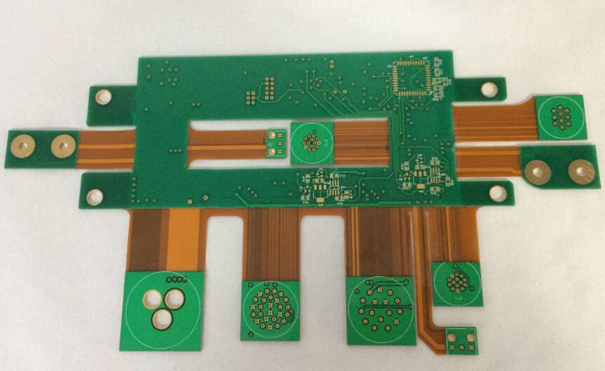
A flexible circuit board is often described as a thin rigid board that bends, and that description leads to bad decisions. The construction is different in kind, not just in thickness. The base is a film rather than a woven glass laminate, the conductors are attached differently, and the protective layer is a separate sheet that has to be shaped and registered like any other feature. Understanding those three parts explains most of the assembly problems that show up later.
What the Stack Is Made Of
Three materials do the work. The insulating film is the base layer, and in most designs it is polyimide film, chosen for its temperature range and its stability during soldering. The conductor is copper foil, which carries the current and, in a dynamic design, has to survive repeated bending. The adhesive bonds the two together, and in a multilayer construction it also bonds the subassemblies to each other.
The film does more than insulate. It acts as a protective covering that keeps the circuit away from dust and moisture, and it holds the conductors near the neutral axis so that the stress they see during flexing is reduced. Where a flexible circuit needs mechanical support, a rigid element of aluminum or stainless steel is bonded in place to give dimensional stability, a mounting surface for components, and a path for releasing stress.
<img src="https://www.gopcba.com/wp-content/uploads/2024/10/PCB-conformal-coating.jpg" alt="Flexible circuit board construction showing film, adhesive layer and copper” />
Adhesive and Adhesiveless Constructions
Not every stack contains an adhesive layer, and the difference is significant. An adhesiveless construction bonds the copper directly to the film, so the finished circuit is thinner, more flexible, and better at conducting heat away. Removing the adhesive removes its thermal resistance, which matters most in designs that carry power or that must survive a wide temperature range. The trade-off is cost and material availability, since the choice of films and copper is narrower than for a conventional build.
Where adhesive is used, it appears in more than one role. It bonds the film to the copper, it forms the coverlay that protects the finished circuit, and it can act as a cover coating applied by screen printing. Those are different processes with different tolerances, and treating them as one step is a common source of registration errors in the finished part.
Conductors: Rolled and Electrodeposited Copper
Two kinds of copper foil appear in flex, and the choice depends on whether the circuit moves. Electrodeposited copper is plated onto a drum; one side is bright and the other is matte, and the matte surface is usually treated to improve adhesion. Rolled and annealed copper is formed mechanically, which gives it a smoother surface and much better ductility. For a design that flexes repeatedly, rolled copper survives far more cycles before it cracks, and the cost difference is small compared with the cost of a field failure.
Thickness is a separate decision. Thinner copper bends more easily but carries less current, and a flex circuit already dissipates heat less effectively than a rigid board, so a conductor may need to be wider than the same net on FR-4. Designers who use a trace width and current calculation should set the allowable temperature rise conservatively for flex, because there is no thick laminate underneath to spread the heat.
Coverlay and Stiffeners
The coverlay is the flex equivalent of solder mask, and it behaves differently. It is a separate film, usually polyimide with an adhesive backing, laminated over the conductors and opened at the pads. Registration matters in both directions: the openings must expose the full pad, and the edge of the coverlay must not sit so close to a bend that it becomes a crack initiator. Where a connector or a fine-pitch device is mounted, a stiffener is added underneath to give the pad area the rigidity that soldering requires.
Stiffeners are usually polyimide, FR-4, or stainless steel, and the choice changes the assembly profile. A stainless stiffener adds a conductive plane under the part and a thermal mass that alters how quickly a pad heats during reflow. That is often useful, but it has to be accounted for in the reflow profile rather than discovered on the first panel.
Soldering a Fine-Pitch Device on Flex
Hand soldering a quad flat package to a flex circuit follows a sequence that exists to protect the part. Wet the pads and level them with an iron first, so that an oxidized or uneven pad does not leave a weak solder joint. Place the device with a vacuum tool or fine tweezers, align it to the pads, and confirm the orientation before any heat is applied. Tack two diagonally opposite pins, then re-check the alignment, because a part that shifts during the tack is far easier to move before the remaining leads are soldered.
When soldering the rest of the leads, keep the iron tip parallel to each lead and let solder flow into the joint rather than pushing it in, which is how bridges form. Then clean the flux thoroughly. On flex the residue matters more than on a rigid board, because it can trap moisture under the coverlay and because the solvent used to remove it must not attack the adhesive. Finish by inspecting for cold joints under magnification, and clear the flux with a soft brush and a mild solvent, working along the lead direction until no residue remains.
Two-terminal chip parts are simpler. Tin one pad, position the part with tweezers, solder that end, verify the alignment, then solder the other end. The same care about placement accuracy applies, and the mechanisms that move a part out of position are described in SMT component shift causes.
Handling Rules That Prevent Damage
Most flex failures are mechanical, not electrical, and they happen during assembly rather than in the field. Support the board along its length so that no single bend takes the whole load, keep the bend radius generous, and avoid pulling on a cable tail to move the assembly into position. Keep the number of rework cycles low, because each heating and cooling cycle stresses the adhesive and the plated joints, and a joint that passed inspection can still open later.
Storage matters as much as handling. Keep the parts flat and covered so the pads are not contaminated before they reach the line, and avoid stacking them in a way that creases the flexing region. Where the finished assembly will see humidity or condensation, a protective coating is a better answer than relying on the coverlay alone; the options and their trade-offs are covered in conformal coating for board protection.
Reviewing the Design Before Release
Before a flex design goes to the fabricator, check four things that are easy to overlook. Confirm the copper type against the number of bend cycles expected, because electrodeposited copper is the wrong choice for a dynamic bend. Confirm that no plated via sits inside a bend zone. Confirm that the coverlay openings and the stiffener outlines are dimensioned on the same drawing as the outline itself, so that the three cannot drift apart. Finally, confirm that the panel layout leaves enough free edge that handling and singulation will not damage the conductors.
The remaining risk is documentation. A flexible circuit board has more process steps than a rigid board of the same function, and each step has its own tolerance. Recording the film, the copper type, the coverlay thickness, and the stiffener material on the fabrication drawing is what keeps a later revision from substituting a cheaper material and changing the mechanical behavior of the part.
FAQ
How do I know if the construction contains adhesive? Ask for the material stack. An adhesiveless build lists copper and film only; an adhesive-based build lists a bonding layer between them, and it usually appears again as the coverlay adhesive.
Which copper should be used for a dynamic bend? Rolled and annealed copper. It is smoother and far more ductile than electrodeposited foil, so it survives many more bend cycles before cracking.
Why does flex need wider traces than a rigid board? Because the film spreads heat poorly, so the same current produces a larger temperature rise. The width has to be set for a lower allowable rise.
What is the most common assembly mistake? Bending the part during handling to reach a connector. It loads one small region instead of the whole length and starts a crack that appears much later.