
PCB Key Metrics: Warpage, Copper Thickness and Impedance
Three numbers decide whether a finished panel behaves the way the design intended: how flat it stayed, how much copper is actually on the traces, and what impedance the controlled traces present. Each is quoted on a drawing, each is measured in a different way, and each interacts with the other two. A board can meet all three specifications individually and still fail in assembly if the measurement method behind the numbers was never agreed, which is why metric definitions matter as much as the metric values.
Why a Metric Needs a Method
A specification without a measurement method is an opinion. The same copper layer can be measured as base foil thickness, as plated thickness on a surface pad, or as the minimum wall thickness in a barrel, and the three values can differ by a factor of two. Warpage can be measured against a granite plate, on a vacuum chuck or in a reflow oven, and each method gives a different answer.
Agreeing the method, the sample location and the pass or fail limit before production starts turns a specification into a contract. It also tells the fabricator which process controls matter, because a limit that can only be met by holding plating uniformity is a very different request from one that is satisfied by the nominal foil weight alone.
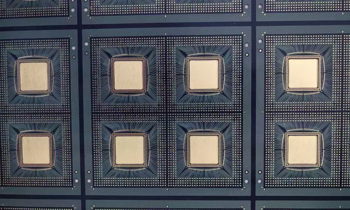
Warpage: How Much Is Too Much
Warpage is the deviation of the board from flat, and it is normally expressed as a percentage of the diagonal or as a maximum deflection over the board length. The acceptable figure depends on what happens next: a board that will be placed on a flat conveyor and printed with paste through a stencil needs to be flat enough to gasket properly, while a board that will be screwed down to a chassis can tolerate considerably more.
Assembly is where warpage turns into yield loss. A board that bows upward touches the stencil in the middle and misses it at the edges, so paste volume varies across the panel and joints at the corners run short. A board that bows downward leaves a gap under the centre and smears paste where it should not be. Both defects appear as random assembly problems until the panel flatness is measured.
Measuring Warpage Reproducibly
The standard method places the board on a flat reference surface and measures the maximum gap beneath it, or measures the deviation of the surface on a coordinate measuring machine. The important detail is that the board must be at a defined temperature and must be free of any load, because both heat and clamping change the shape and can hide or exaggerate a problem.
Where a reflow process is involved, a room temperature measurement is not sufficient. A board can be flat when it is cold and bow significantly at solder temperature, and the difference is caused by the copper distribution, the laminate and the lamination cycle. That is why a balanced copper design and a symmetric stackup matter: they keep the shape stable across the temperature range the board will actually see. Our notes on warpage causes and fixes cover the process side.

Copper Thickness and Where It Is Measured
The copper thickness that matters electrically is the minimum anywhere on the conductor, not the nominal weight of the foil that started the process. Plating is thicker at the panel edges, at isolated features and near hole entries, and thinner in dense areas and in the middle of a long barrel. A design that needs a specific current capacity has to be checked against the thinnest point, which is usually inside a plated through hole.
Measurement is normally by microsection on a coupon, supplemented by X-ray fluorescence on surface features. The coupon should be built with the same copper density and the same hole geometry as the product, because a coupon with a different pattern plates differently and reports a thickness the product never achieves.
Impedance Control and Coupon Design
Impedance control depends on four things at once: the trace width, the dielectric thickness above and below the trace, the dielectric constant of the material, and the copper thickness. All four vary in production, and the tolerance on the finished impedance is the sum of their effects. A coupon that measures only one of them says very little about the finished board.
The coupon should therefore be built with the same geometry as the product trace it represents, measured on the same panel, and tested with a method agreed in advance. Time domain reflectometry on a coupon is the usual production check, and its results should be recorded against the lot number. Where a discontinuity appears in the measured profile, our notes on impedance discontinuity analysis describe how to localise it.
How the Three Metrics Interact
The three are not independent. Copper distribution decides warpage, because unbalanced copper makes the laminate bow during lamination and reflow. Copper thickness decides impedance, because a heavier trace is a thicker conductor and presents a lower impedance for the same geometry. Dielectric thickness affects both impedance and flatness, since a thinner layer reduces mechanical stiffness.
That coupling is why changing one parameter to fix a problem often disturbs another. Increasing copper to improve current capacity shifts the impedance; thinning the dielectric to hit an impedance target reduces stiffness and makes warpage worse. The usual solution is to adjust the stackup as a whole, and to verify the result with a coupon that measures all three.
Acceptance Criteria and Sampling
Acceptance criteria belong on the drawing with the sample plan attached. Which boards are measured, how many samples per panel, whether the measurement is destructive, and what happens when a result sits at the edge of the window all need to be stated. A limit that is only checked once at qualification does not control production.
Sampling should be tied to risk. Impedance is normally checked per lot on a coupon; copper thickness by microsection on the first article and periodically thereafter; warpage on a sample from every panel for products that are sensitive to flatness. The figures in PCB manufacturing tolerances give a starting point for each of the three. Our notes on PCB yield and quality control show how the results feed back into the process.
Writing Metrics into a Drawing
Put each metric on the drawing with its value, its tolerance, its measurement method and its sample plan. Name the reference surface for warpage, the coupon design for impedance and the location for copper measurement, because the location is often what decides pass or fail. Where a metric cannot be measured non destructively, say what the destructive test is and who performs it.
Then keep the definitions stable across revisions. A change to the measurement method between two production lots invalidates the comparison and makes it impossible to tell whether the process moved or the yardstick did. Recording the method revision alongside each result is a small discipline that prevents a large argument.
FAQ
What warpage limit should be specified? It depends on the assembly process. Board handling and stencil printing usually need better flatness than a chassis mounted design, and the figure should be quoted with the reference surface and the measurement temperature.
Is nominal copper weight the same as finished thickness? No. Plating adds copper on the surface and in the barrel, and the distribution is not uniform, so the finished minimum is generally higher than the base foil but lower at the thin points than the nominal figure suggests.
Can impedance be guaranteed without a coupon? It can be calculated and it can be controlled by process, but the coupon is the evidence. Where impedance is critical, the coupon should be built into the production panel and measured per lot.