Multilayer PCB Prototype Fabrication Flow
A multilayer prototype is not a smaller version of a production run. It is a test of the design data, of the fabricator and of the design rules, and it is built by the same sequence of operations that a production panel will follow. Knowing that sequence is what lets a designer read a fabrication quotation and understand what is being bought.
This article follows a multilayer PCB prototype from the moment the data arrives to the moment the boards are electrically tested, describing what each step does and what the designer contributes to it.
Why a Multilayer Prototype Is Built First
The purpose of a prototype is to find out whether the design and the fabricator agree. The data may contain a pad that is smaller than the drill can register to, a clearance that the etching process cannot hold, or a stack-up that the lamination press will not deliver flat. None of those appear on a screen.
Building a small quantity first also establishes the process before volume. The parameters that are settled during the prototype, the drill sizes that worked, the plating thickness that was achieved and the surface finish that behaved, are the ones that the production panel will use. The requirements that a multilayer prototype has to satisfy cover the data side of the same transaction.
Order Review, Data and Cutting
The first operation happens before any material is touched. The fabrication data is checked against the purchase specification: layer count, finished thickness, copper weight, minimum line width and spacing, hole sizes and the surface finish. Where an item cannot be produced as drawn, the fabricator either proposes a change or asks for a decision.
Cutting then reduces the large panel stock to the working size defined by the manufacturing instruction. The sheet is cut with the grain considered, the corners are rounded so that the panel does not catch in the handling equipment, and the edges are dressed. The size is chosen so that the panel fits the plating line and the drilling machine with room for the tooling holes.
Drilling, Registration and Panel Handling
Drilling is the step that sets the registration budget for everything that follows. The panel is pinned on the machine, the holes are drilled to the sizes in the drill table, and the holes are inspected and any that are out of tolerance are recorded. The position of every hole relative to the tooling system is what the inner-layer pattern will be aligned to later.
The condition of the hole wall matters as much as its position. A drill that is worn or a feed rate that is too high will smear the resin across the copper of the inner layers, and a smear is an insulating film between the copper and the plating that is supposed to connect to it. Desmearing removes it, and it is a step that is easy to omit and impossible to see.
Electroless Copper and Panel Plating
The drilled panel is not electrically conductive inside the holes, so the first thing plated is a very thin layer deposited by chemical means rather than by current. Electroless copper covers the resin walls of the hole and connects them to the copper of the inner layers, and it is thin enough that it only has to be continuous.
That thin layer is then reinforced by electroplating until the required copper thickness is reached. The plating has to reach the middle of the panel as well as the edges, which is why the current distribution, the anode arrangement and the agitation of the bath are all part of the process control rather than details. Thin plating in the centre of a panel is a reliability problem that appears long after the boards have shipped.
Inner Layers and Lamination
Before any of the outer-layer work can start, the inner layers have been imaged, etched, inspected and bonded. Each inner core is processed like a thin double-sided board, checked for opens and shorts, and then stacked with bonding sheets between the cores and copper foils on the outside.
The stack is registered against the tooling system and pressed under heat and pressure, and the resin flows and cures to form a single rigid panel. Registration at this stage is what all the later drilling and imaging steps inherit, which is why the layer-to-layer alignment of a finished board is decided long before the first hole is drilled.
Pattern Transfer: Dry Film or Liquid Resist
After plating, the panel carries copper everywhere, including the areas that will eventually be etched away. To define the pattern, a resist is applied to the surface: either a photosensitive dry film that is laminated onto the copper, or a liquid resist that is printed and dried.
The resist is exposed through a film that carries the artwork, and the exposed or unexposed areas, depending on whether the resist is negative or positive, are dissolved away in development. What remains is a mask that covers exactly the copper the circuit needs. Dry film gives a uniform thickness and is easier to control; liquid resist conforms better to a rough surface but is more sensitive to how it is applied.
Pattern Plating, Stripping and Etching
With the resist in place, the exposed copper is plated up to the required thickness and then coated with a thin layer of tin or a tin alloy. That tin layer is the etch resist: it protects the circuits while the surrounding copper is removed.
The resist is then stripped in a chemical bath and the panel is etched, which removes the thin copper that was never plated. Because the plated circuits are protected by tin and the laminate is protected by nothing, the etching has to be closely controlled, and the defects that appear in plated and etched copper are the reason for the process control. After etching, the tin is removed and the circuits stand exposed.
Solder Mask and Legend
The solder mask is printed onto the panel as a photosensitive coating, exposed through a film that opens the areas where solder must reach the copper, and developed so that the openings are clean. It is then cured, and the cure has to be complete without being so severe that the coating becomes brittle.
The legend is printed after the mask, and it carries the reference designators and identification marks. It sits clear of the mask openings, and it has to remain legible after assembly, which is why it is sized according to the print process that will produce it rather than to the space that happens to be available.
Surface Finish: Gold Fingers or Hot Air Levelling
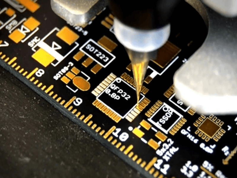
Exposed copper will not stay solderable for long, so a finish is applied. Boards with an edge connector receive a plated nickel and gold layer on the contact fingers, which gives a hard, wear-resistant surface for repeated insertion. Other exposed pads receive whichever finish the specification calls for.
For boards finished with hot air solder levelling, the panel is coated with flux, passed through molten solder and then subjected to a blast of hot air that clears the holes and levels the coating. The process leaves a solderable surface, and the hole clearing step is what keeps the connectors and through-hole parts insertable.
Profiling and Electrical Test
The board outline is produced by routing with a machine or by punching with a die, and the two are not identical in accuracy. Machine routing gives the tighter profile and is used for prototypes and for shapes that a die cannot produce; punching is faster and cheaper and is used in volume.
Every board is then tested electrically, which catches the opens and shorts that visual inspection cannot see. A flying probe or a bed-of-nails fixture compares the measured connectivity with the netlist, and a board that fails is either repaired or rejected. This is the last operation in the chain, and it is also the one that decides whether the design rules were good enough. The rules that keep a board manufacturable are what make this step uneventful.
FAQ
How long does a multilayer prototype take? The process above runs continuously through drilling, plating, imaging, lamination, mask, finish and test, so the duration is set by the queue at each station rather than by any single step.
Which steps can be changed to reduce cost? The finish, the profile method and the board size are the three that most directly affect price, along with the number of layers and the minimum feature size the design uses.
Why test every board rather than sampling? An open circuit on a prototype is expensive to find later, and the boards are few. Testing all of them is affordable at this stage and it validates the fabrication data rather than only the panels.