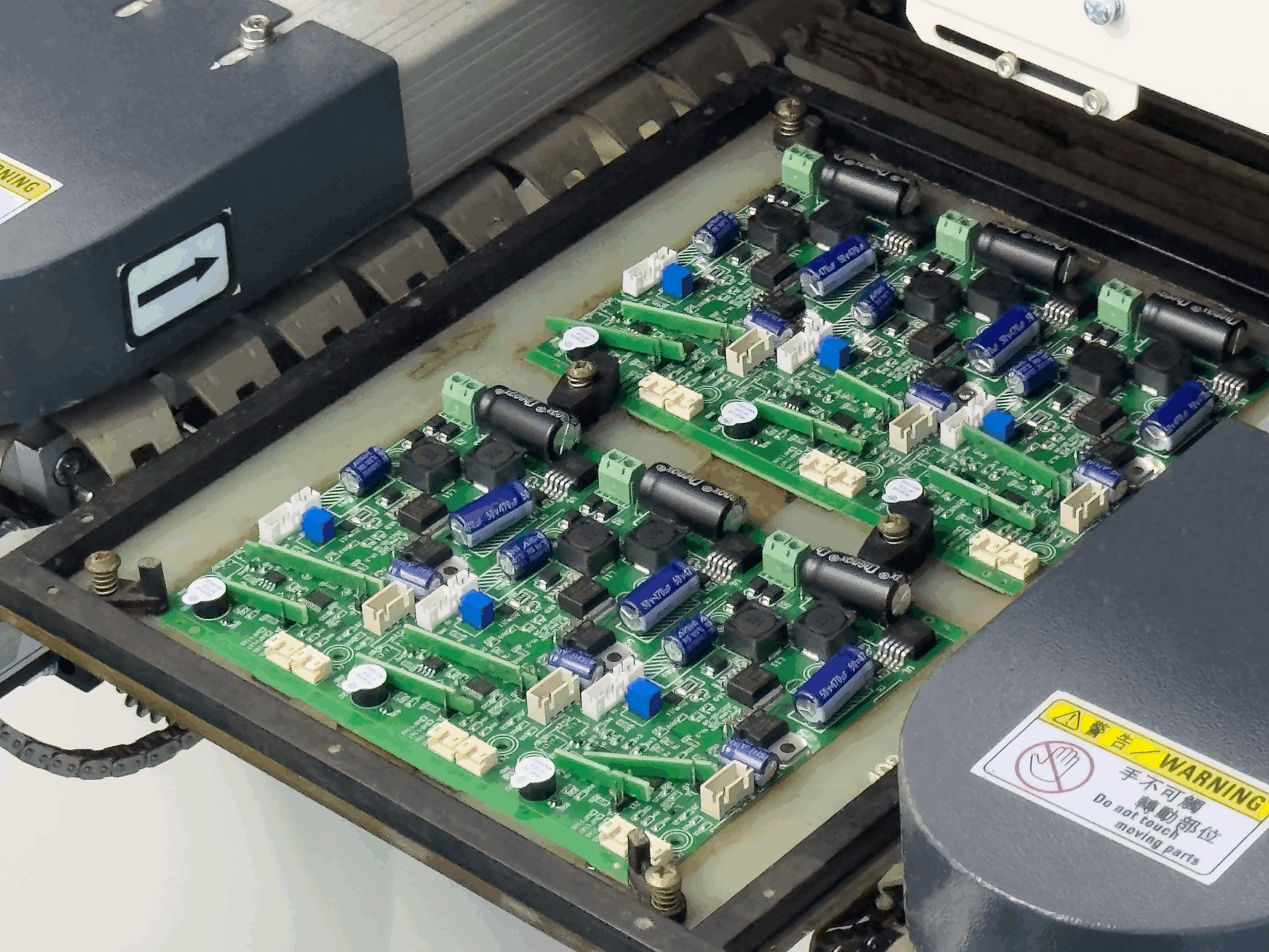
Board Strain Measurement During Assembly
A board that flexes by a fraction of a millimetre during assembly can crack a multilayer ceramic capacitor or lift a solder joint, and the damage may not appear until months later in the field. Because the cause is mechanical and the effect is electrical, the two are rarely connected during an investigation. Measuring board strain with a gauge turns that invisible risk into a number that a production line can control.
How Mechanical Stress Damages Assemblies
A multilayer ceramic capacitor is a stack of brittle dielectric layers with metal electrodes, and it is strong in compression but weak in tension. When the board beneath it bends, the capacitor is forced to follow, and the tensile stress concentrates at the termination. A crack propagates through the ceramic, often without breaking the part in two, and the resulting leakage or intermittent short appears later under thermal cycling.
Solder joints suffer the same way, particularly on large packages and on parts with a stiff body. A leadless component transfers the board deflection directly into the joint, and repeated flexing produces a fatigue crack that starts at the fillet. Both failure modes are cumulative, so a single over-stress event during handling can be the start of a crack that grows to failure in service.
Measuring Strain with Gauges
A strain gauge is a small resistive element bonded to the board surface, with its axis aligned to the direction in which strain is expected. As the board flexes, the gauge stretches or compresses and its resistance changes in proportion. A bridge circuit and a data logger convert that change into microstrain, which is the unit used in every assembly specification.
Placement of the gauges is the critical decision. They should be bonded near the components that are most at risk, with their axis aligned to the direction of maximum bending, and they should be on the surface that goes into tension, because ceramics fail in tension. On a typical board, gauges are placed near the corners, close to large ceramic capacitors, and adjacent to the panel break lines.

Strain Limits and What They Mean
The widely used limits come from capacitor manufacturer research. A peak strain of around 500 microstrain is often quoted for a single event, with a recommendation to stay below 300 microstrain for repeated operations and below 200 for the most sensitive parts. These are guidelines rather than hard boundaries, and the acceptable figure depends on the component size, the orientation of the part relative to the bend, and the number of events.
Peak strain and strain rate are both relevant. A fast event produces a higher strain rate, which causes more flexural damage in a brittle material, so a slow bend to the same deflection is less harmful than a sharp one. This is why a depaneling process that snaps a board quickly can cause more damage than the deflection alone would suggest.
Sources of Strain in Assembly
Several common operations generate strain. Depaneling by hand, by a snap-off tab, or by a dull router bit is the largest single source in most factories. Screwing a board into an enclosure that is not flat forces it to conform and produces a sustained bend. Connector insertion, particularly for a press-fit or a stiff board-to-board part, produces a local deflection that can be large.
Board handling adds to the total. A board supported only at its edges and pushed in the centre will bow, and a stack of boards carried without a tray will flex under its own weight. Thermal processes contribute as well, since the difference in expansion between the board and a heavy component produces a strain that the joint must absorb on every cycle.
Depaneling and Board Support
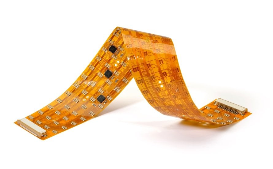
Depaneling deserves specific attention because it is both the largest and the most controllable source. Routing with a sharp bit and a properly supported board keeps the strain low, while snapping a tab by hand produces a shock that is difficult to control. Where a tab must be broken, a fixture that supports the board on both sides of the break line and applies a controlled force is far safer than a manual snap.
Support is the other half of the answer. A board should be held flat on a rigid surface during any operation that applies a force, and the support should be close to the point of application so that the unsupported span is short. Vacuum fixtures and custom pallets both achieve this, and their cost is small compared with the value of the boards they protect.
Handling and Fixture Design
Handling rules should be written down and taught. Support the board at two points close together when lifting it, avoid pressing on the middle of an unsupported area, and never use a board as a lever when inserting a connector. Trays with the correct pocket depth prevent a stack from flexing, and their use should be mandatory rather than optional during peak production.
Fixture design follows the same principle. Screw bosses should be flat and coplanar, so that tightening the fastener does not bend the board. Where an enclosure is not flat, the board should be allowed to float rather than be forced into shape, which can be achieved with a compliant washer or a slightly oversized hole. Reviewing the mechanical design with the same care as the electrical one prevents a large class of field failures.
Setting a Factory Limit
A factory limit should state the maximum strain, the strain rate, and the operations to which it applies. The limit is then verified with gauges on the most sensitive board in the product family, and the results are recorded so that a change in process can be compared. Where a gauge cannot be used, a deflection measurement with a dial indicator on a representative support arrangement gives an approximate but useful check.
A measurement programme should also include the prototype assembly stage, not only volume production. Hand assembly, bench rework, and improvised fixtures generate some of the highest strains a board will ever see, and the results are often worse than anything the production line produces. Gauging a prototype build identifies the risky operations while a design change is still cheap.
The measurement programme pays for itself quickly. A single cracked capacitor found in the field is expensive to diagnose, and the corrective action is often a change to a fixture or a handling instruction that strain measurement would have identified in an afternoon. Combined with the mounting and outline design rules, it gives the product a mechanical margin rather than a mechanical assumption.
FAQ
What strain limit should a factory use? A common working figure is 500 microstrain for a single event and 300 microstrain for repeated operations, with tighter limits for large ceramic parts and for parts oriented across the bend.
Where should gauges be placed? Near the components most at risk, on the tension side of the bend, with the gauge axis aligned to the direction of maximum deflection. Corners and areas close to panel break lines are the usual locations.
Does strain measurement replace process control? No. It identifies where the risk is and whether a change helped, but the everyday protection comes from fixtures, trays, and handling rules that keep the deflection small.