Depaneling: Burrs, Chipping And Edge Quality
Depaneling, the operation that separates boards from a panel, is the last mechanical step a board undergoes before assembly, and it is the operation most likely to damage it. A routed edge that is rough, a laminated board that cracks between the layers, a ceramic capacitor that fractures as the panel flexes: each of these is a defect created at the end of a process that was otherwise under control.
This article covers the two common separation methods, the defects each one produces, and the design and process choices that reduce them.
The choice between the methods is usually made early, when the panel is laid out, and it constrains the layout for the rest of the design.
Routing And Its Defects
Routing cuts the outline with a rotating bit, following a path that leaves small tabs to hold the board in the panel. The edge quality depends on the bit, the spindle speed, the feed rate and the number of times the tool has been used. A worn bit or a feed rate that is too aggressive produces a rough edge, and a dull tool generates heat that can smear the resin rather than cutting it cleanly.
The characteristic defects are burrs on the copper at the board edge and delamination between the layers near the cut. Burrs are a problem where the edge carries a connector or where the board slides into a guide, and delamination is a reliability risk because it creates a path for moisture. Board outline and mounting design rules set the clearance that keeps copper away from the cut, which reduces both defects.
<img src="https://www.gopcba.com/wp-content/uploads/2026/06/SMT-Production-Line.jpg" alt="Routed board edge showing a copper burr” />
V-Scoring And Its Defects
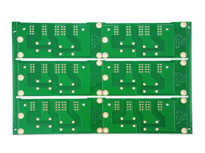
V-scoring cuts a groove on both sides of the panel along a straight line, leaving a web of material that is snapped to separate the boards. The method is fast and cheap and it produces a clean edge, but it requires straight lines across the whole panel and a board thickness and web thickness that will break predictably.
Its defects are different. The web can break unevenly, leaving a rough lip on one side. The scoring wheels wear, which changes the geometry of the groove over a production run. And because the scoring is mechanical, it introduces stress into the board, which can crack components placed too close to the score line. The panelisation design rules for scoring exist largely to control that stress.
Which Method Fits Which Board
Routing suits boards with curved or irregular outlines, boards with components close to the edge, and thick boards where a score would be unreliable. Scoring suits rectangular boards with straight edges, thin to medium thickness, and a high production volume where the speed of the process is valuable.
Mixed outlines are possible, with a score along the long sides and routing at the corners, but the combination adds handling steps. Where the panel is dense, the separation method is often the constraint that decides how the boards are arranged rather than the other way around.
<img src="https://www.gopcba.com/wp-content/uploads/2026/05/人形机器人PCBA.png" alt="V-score groove along a panel edge” />
Stress And Component Damage
Both methods apply mechanical stress to the board, and the stress is transmitted to whatever is mounted on it. The most sensitive components are multilayer ceramic capacitors, which crack under bending and fail later as a short, and large packages whose solder joints can be strained by a flexed board.
Keeping components away from the separation line is the first defence. Where a component must be near the edge, the board should be supported during separation so that the bending is limited, and the separation force should be applied by a tool that does not twist the board. The principles behind such defects, including the displacement of components during assembly, are worth reviewing when a component is placed close to a break line.
It is worth measuring an edge rather than describing it. A cross section through the board edge shows the burr height, the condition of the copper foil at the cut and whether the laminate has separated. That measurement turns a subjective judgement about edge quality into a number that can be specified and inspected, which is what makes a process change verifiable.
The Cut Edge And The Finished Product
The edge of a finished board is not merely cosmetic. A rough edge can snag a cable, interfere with a guide rail and produce conductive debris that finds its way onto a pad. Copper exposed at the edge by a burr is also a corrosion site and, where the board carries mains or high voltage, a creepage path that was not accounted for.
For these reasons the outline tolerance and the allowed burr size are part of the fabrication specification rather than an afterthought. The manufacturing tolerances that apply to the outline should be stated with the same care as those that apply to the copper.
Debris is the other hazard the operation creates. Cutting produces fine particles of resin and copper, and a particle that lands on a pad before assembly produces a poor joint or a short that appears at test. Extraction and cleaning after separation is part of the process, not an optional addition, and the cleaning has to be compatible with the components already mounted.
Improving The Process
Four process parameters account for most of the variation. The condition of the cutting tool or the scoring wheel is the first, and replacing tools on a schedule rather than on failure is the most effective single change. The feed rate and spindle speed are the second, and they should be set by the material rather than by the maximum the machine can achieve.
Support of the panel during the operation is the third. A panel that is not held flat flexes under the cutting force, which produces both a rougher edge and more stress in the components. The fourth is handling after separation, because a burr formed at separation can be pressed into the board by the next operation if boards are stacked or moved carelessly.
Designing For Clean Separation
The layout decisions that make separation clean are simple and they cost nothing at design time. Keep copper and components a defined distance from the outline, choose the method before the panel is arranged, keep the break lines straight if scoring is intended, and leave room for the tabs if routing is intended.
It is also worth considering the order of operations. Where the design allows, separating the panel after reflow rather than before is standard, because handling loose boards through the assembly line is more difficult and more damaging than handling a panel. The separation stress then arrives at the end, when the components are already attached and the risk of cracking them is highest, which is why the clearances and the support matter more in that sequence.
Where the product requires a particularly clean edge, laser separation removes the mechanical stress entirely by cutting with a focused beam. It is slower and more expensive, and it is used where the board is thin, brittle or densely populated near the outline and mechanical methods cannot meet the requirement.
FAQ
Can a burr be removed after separation? It can be reduced by a deburring operation, but the operation itself can damage the edge or introduce debris. Preventing the burr by controlling the tool is preferable.
Does scoring affect the board’s electrical performance? It does not change the routing, but the stress it introduces can crack components near the score line. The material removed by the groove also changes the mechanical stiffness of the board, which matters where the board is clamped in a housing.
Should the panel be separated before or after assembly? After, in most volume production, because the panel is easier to handle through the line. The clearances and the support during separation then have to account for the mounted components.