
Accelerometer Mounting and PCB Design
A MEMS accelerometer reports the motion of the package it is soldered into, which means it measures the board as much as the machine. Everything the board does under vibration, from flexing in the middle to ringing at a mounting screw, appears in the output as if it were real motion. Getting a useful measurement therefore starts with the mechanical design rather than the register settings.
How a MEMS Accelerometer Senses Motion
Inside the package a small proof mass is suspended on silicon springs above a fixed electrode pattern. Acceleration displaces the mass, the gap between the mass and the electrodes changes, and the resulting capacitance change is converted to a digital value by the interface circuit on the same die. The springs and the mass define the resonant frequency of the sensing element, typically a few kilohertz.
The sensing element responds to acceleration along one, two or three axes depending on the part. A three axis device has three separate masses oriented at right angles, so the sensitive directions are defined by the package outline and by the die attach orientation. Rotating the package therefore rotates the coordinate system that the firmware reports.
Because the output is proportional to acceleration, gravity appears as a constant offset when the axis is vertical. A device at rest reports one g on the axis aligned with the vertical, and that reading is the basis of tilt measurement as well as the easiest way to verify that the part is working and correctly oriented.
Choosing the Range and Bandwidth
The measurement range and the resolution are linked by the converter inside the device. A part configured for plus or minus two g resolves small movements well, while the same part set to plus or minus sixteen g uses the same converter over a wider span and therefore resolves eight times less. Selecting the range is a trade between how large a shock the sensor must survive and how small a movement it must resolve.
Bandwidth matters in the same way. The output data rate sets how often the signal is sampled, and the internal filter limits the band above it. A rate that is too low aliases high frequency vibration down into the band of interest, where it appears as a slow motion that does not exist. Setting the rate at least five times the highest frequency of interest keeps that error small.
noise density is the specification that ties the two together. It is quoted in micrograms per root hertz, and multiplying it by the square root of the bandwidth gives the root mean square noise that the measurement will show. Doubling the bandwidth therefore increases the noise by about forty percent, which is why an unnecessary high data rate costs accuracy as well as power.
Mechanical Resonance and Mounting
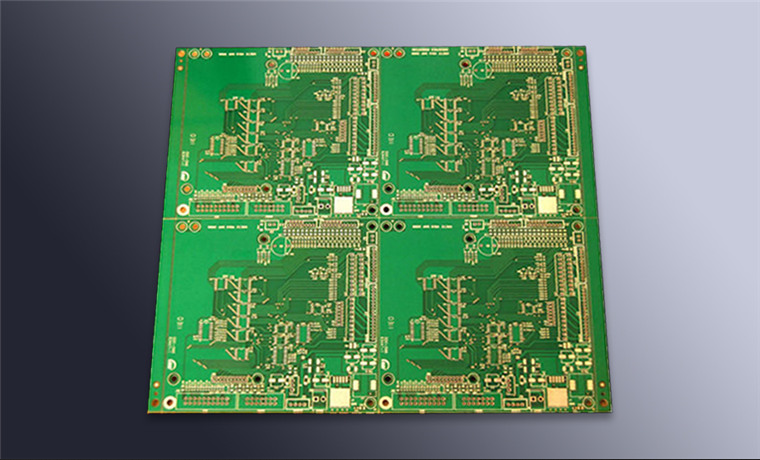
The board is a spring, and the sensor is the mass on the end of it. A typical sensor board mounted at two corners has a first bending mode somewhere between several hundred hertz and a few kilohertz, and vibration near that frequency is amplified rather than measured. The amplified motion appears in the output as a plausible but entirely false signal.
The fix is mechanical. Add mounting screws so that the span between supports is short, and place the sensor close to a mounting point rather than in the middle of a panel. Where the board must be large, a stiffener or a thicker laminate raises the resonance above the band of interest. mechanical resonance should be measured on a prototype with a shaker and an impact test rather than assumed.
mounting orientation is the other mechanical decision. The sensor should be aligned so that the axis of interest is perpendicular to the board surface or along the direction of motion, whichever the application requires, and the assembly drawing should show that orientation explicitly. A part rotated by ninety degrees during assembly will still work, which is why the error is often found late.
Solder Joint and Package Stress
Board bending during assembly puts stress on the solder joints of a small package, and the stress continues after the board is mounted if the assembly applies a permanent strain. A MEMS package is more sensitive than most, because the same strain that reaches the joint also reaches the die attach and the sensing element, where it appears as an offset.
Keep the package away from the board edge and away from mounting holes, where the strain from a screw is concentrated. Avoid placing the sensor next to a connector that is inserted and removed in the field, and avoid mounting it over a stiffener boundary where the local stiffness changes abruptly. These are the same rules used for any strain sensitive component, and our article on board quality characteristics reviews them from the fabrication side.
Zero ohm offset is not recoverable in software, but it is measurable. Comparing the output of a board before and after it is screwed down, and again after thermal cycling, shows how much strain the assembly applies. If the offset changes by more than the resolution of interest, the mechanical design needs attention before the firmware does.
Supply, Reference and Noise
The sensing element resolves accelerations far below the level of the supply noise, so the interface circuit has to be quiet. Decouple the supply with a ceramic capacitor within a few millimetres of the pin, add a small series ferrite where the rail is shared with switching circuitry, and keep the supply trace away from the digital lines that carry the sensor data.
Some parts provide a reference output that should be bypassed and, where an external reference is used, it has to be as quiet as the supply. A reference that moves with temperature shifts the zero g offset, which in a tilt application appears as an angle error that changes with the weather. Checking the offset drift over temperature is a quick way to confirm that the reference and the supply are adequate.
The data interface itself is a source of noise. Serial clock lines running past the sensor couple into the analogue section, and the coupling appears as a tone at the clock frequency in the spectrum. Keep those lines short, route them over a continuous ground plane, and where possible use a lower clock rate for the sensor bus than for the rest of the system.
Layout and Signal Integrity
Place the sensor in a quiet corner of the board with a solid ground plane beneath it, and keep switching regulators, motor drivers and relay coils away. The analogue area should be separated from the digital area in the same way as any mixed signal design, which is the partition described in mixed signal board design, and the sensor belongs firmly on the quiet side.
Keep the traces between the sensor and the controller short, and avoid vias in the critical signal path where the same net also carries a fast clock. Where the sensor is connected by a cable, the cable should be short, screened and, if possible, twisted, because a long cable acts as an antenna and as a mechanical spring, both of which degrade the measurement.
Power supply return paths deserve the same attention. A return current that shares copper with the sensor ground produces a voltage that the sensor cannot distinguish from acceleration, so the supply for the sensor should be routed with its own return to a single point. Our article on EMI suppression design gives the general method for tracing those paths.
Calibration and Self Test
Offset and sensitivity calibration turn a raw reading into a useful measurement, and both are simple because the sensor responds linearly. The zero g offset is measured with the axis horizontal, and the sensitivity is confirmed by turning the board so that the axis is vertical, where the output should read one g. A 180 degree rotation gives a second point and cancels the effect of any residual tilt in the fixture.
Most devices include a self test that applies an electrostatic force to the proof mass and checks that the output responds. Running it at power up confirms that the sensing element is intact and that the mechanical path is free, which is valuable in equipment that is installed where it cannot easily be serviced. The self test does not verify the mounting or the solder joints, so it cannot replace an offset check in the final assembly.
The remaining error after calibration comes from cross axis sensitivity, which is a small response of one axis to acceleration along another, and from nonlinearity at the extremes of the range. Both are quoted on the datasheet and both are worth including in the error budget. If the system needs better performance than the part can deliver, the answer is a different sensor rather than more calibration.
FAQ
Can I mount an accelerometer on a flexible bracket? The bracket will have its own resonance, usually below the board resonance, and it will amplify motion near that frequency. Use a stiff bracket and confirm the resonance with an impact test.
How do I detect a damaged solder joint? Compare the zero g offset before and after thermal cycling, and inspect the joint with X-ray. A crack usually shows as a step change in offset rather than a gradual drift, and it is often intermittent with temperature.
Does the mounting screw torque matter? It does on a thin board. High torque bows the board and shifts the offset, so specify a torque value and verify the offset with the production fasteners in place.