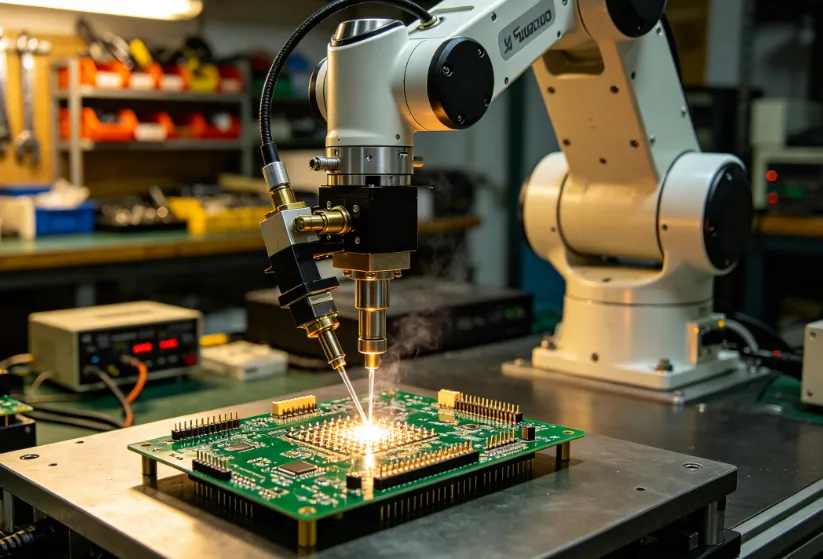
Reflow Assembly of Flexible and Rigid Flex Circuits
A flexible circuit is thin, it moves and it is soldered in the same process as a rigid board. Each of those properties changes how the reflow has to be controlled.
Why Flex Behaves Differently
The material is thin, so it heats quickly and it also cools quickly. The profile that suits a rigid board can overheat a flex circuit before the components and the solder have equalised.
The circuit also moves, and the movement during reflow can displace a placed component. The support is part of the process rather than an accessory. Our thermal mass notes describe the same issue on a rigid board with a large copper area.
Support and Fixturing
The circuit is usually held flat on a carrier for printing and placement, with an adhesive or a vacuum. The carrier has to release without stretching the circuit.
A circuit that is stretched during the process springs back afterwards and the joints are loaded. Our carrier notes describe the design that avoids it.
Moisture in the Base Material
A polyimide circuit absorbs moisture and it releases it during reflow. The release causes blistering between the coverlay and the conductor, which appears as a bubble rather than as a joint defect.
A bake before assembly is the usual measure, and the schedule should come from the material supplier rather than from a general rule. Our storage notes describe the control.
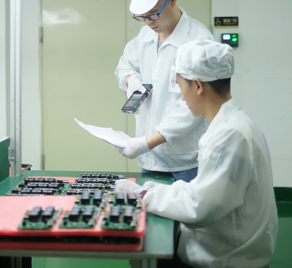
The Rigid Flex Transition
At the transition between the rigid and the flexible section, the thickness changes and so does the thermal mass. The transition is where the profile is hardest to satisfy.
Components should not be placed close to the transition, and the stiffener should end before the flexible area begins to bend. Our flex processing notes describe the stack.
Handling
A flex circuit is easily creased and a crease is a permanent conductor crack. The handling should keep the bend radius above the minimum everywhere, including in the packaging.
The minimum radius depends on the construction and on whether the bend is static or dynamic. Our bendable notes describe the limit.
Stiffeners and Their Attachment
A stiffener is bonded to the circuit for a connector or for a component that needs rigidity. The bond has to survive the reflow and the adhesive must not outgas into the oven.
The stiffener edge is a step in the assembly, so the stencil has to accommodate it or the print is uneven. Our stencil notes describe the step options.
Verification
The verification is the profile measured on the circuit rather than on a rigid sample, the joint appearance, and a bend test on a sample to the minimum radius.
The bend test should be performed on an assembled sample, because the joints are what fail at the bend. Our quality notes describe how the result is recorded.
Process Control and Verification
On a design of this kind, bend radius is the item that decides how the rest of the board is arranged. Documenting the assumption is part of the design work, and a short note on the drawing prevents a question that would otherwise arrive a day later and cost a day of schedule. The process window is set by the narrowest step in the flow, so an improvement anywhere else shows up as margin rather than as yield until that step is addressed.
A short note on the drawing about handling, storage or packaging is often worth more than an extra decimal place on a tolerance. Where a value sits close to a process limit, the drawing should say so, since the shop can then open the process window rather than working to a nominal figure that carries no tolerance.
A stack-up that is drawn rather than described removes most of the ambiguity from a quotation, and it lets the fabricator price the board against the dielectric and copper weights that will actually be used. Where the requirement is not written down, the shop supplies its own default, and the default is chosen for the process rather than for the design.
The measurements that matter are the repeatable ones: conductor width and spacing, annular ring, finished hole size, plating thickness and surface finish are all verifiable on a coupon that travels with the panel. Running a first article through the same checks as the production panel confirms that the two agree, and that comparison is the cheapest form of process control available at prototype stage.
Keeping a sample from the panel turns a dispute into a measurement, because the same coupon can be re-examined by both parties without rebuilding the batch.
Process Control and Verification
On a design of this kind, bend radius is the item that decides how the rest of the board is arranged. Documenting the assumption is part of the design work, and a short note on the drawing prevents a question that would otherwise arrive a day later and cost a day of schedule. The process window is set by the narrowest step in the flow, so an improvement anywhere else shows up as margin rather than as yield until that step is addressed.
A short note on the drawing about handling, storage or packaging is often worth more than an extra decimal place on a tolerance. Where a value sits close to a process limit, the drawing should say so, since the shop can then open the process window rather than working to a nominal figure that carries no tolerance.
A stack-up that is drawn rather than described removes most of the ambiguity from a quotation, and it lets the fabricator price the board against the dielectric and copper weights that will actually be used.
Process Control and Verification
On a design of this kind, bend radius is the item that decides how the rest of the board is arranged. Documenting the assumption is part of the design work, and a short note on the drawing prevents a question that would otherwise arrive a day later and cost a day of schedule. The process window is set by the narrowest step in the flow, so an improvement anywhere else shows up as margin rather than as yield until that step is addressed.
A short note on the drawing about handling, storage or packaging is often worth more than an extra decimal place on a tolerance.
Process Control and Verification
On a design of this kind, bend radius is the item that decides how the rest of the board is arranged. Documenting the assumption is part of the design work, and a short note on the drawing prevents a question that would otherwise arrive a day later and cost a day of schedule. The process window is set by the narrowest step in the flow, so an improvement anywhere else shows up as margin rather than as yield until that step is addressed.
A first article check confirms that the process and the drawing agree on the points listed above, and that the coupon data supports the values used in the design.
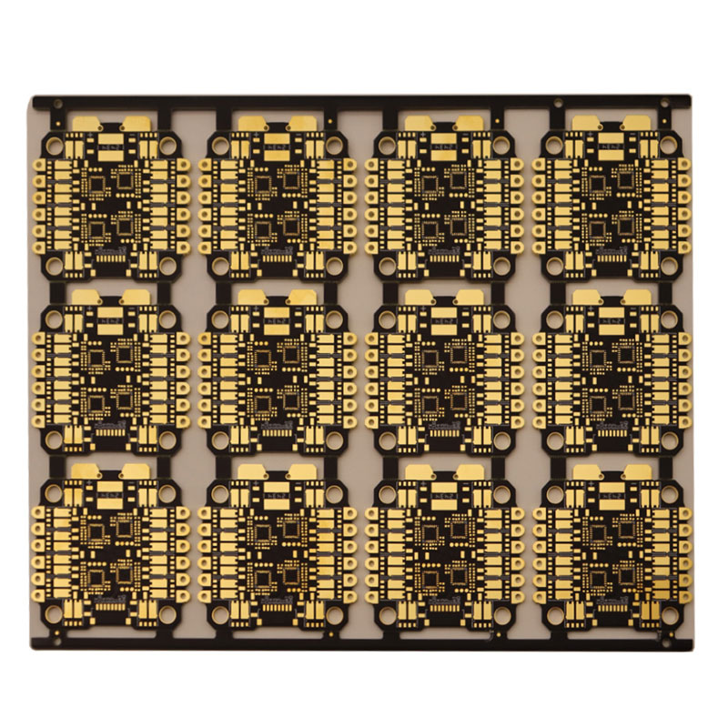
Where a measurement falls outside the expected window, the sample is retained so that the cause can be established before the balance of the batch is released.
FAQ
Can a flex circuit be reflowed on a rigid pallet? It can, and the pallet must support the circuit over its whole area or the unsupported part will sag and the placement will move.
Does a stiffener need to be bonded before assembly? It is usually bonded by the fabricator, because the adhesive has to be cured under pressure.
What does gopcb provide for flex assembly? We provide support and fixturing that holds the circuit without stretching it, bake schedules from the material data, profiles measured on the flex circuit itself, layout rules at the rigid flex transition, stiffener bonding and stencil accommodation, and bend testing of the assembled sample.