Depanelising and Routing Quality
Depanelising is the last mechanical operation before a board becomes a product, and it is one of the few remaining processes where a good board can be destroyed by technique. Routers, v-score breakers, tab cutters and laser systems all separate panels, and each of them introduces stress at the moment of separation. Cracks in the laminate, lifted pads near the break line, hairline fractures in solder joints and burrs along the edge are the usual consequences of a separation process that was set up by feel.
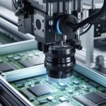
<img src="https://www.gopcba.com/wp-content/uploads/2025/05/DIP拉线风彩.jpg" alt="Router bit separating a board from a panel” />
Stress and Where It Lands
Any separation method applies force to the panel, and the force travels through the board until it finds somewhere to release. The path it takes depends on the panel design: a break line close to a row of components concentrates stress under them, while a generous tab area spreads it out. Because solder joints are brittle and laminate is not particularly tough in tension, the damage usually appears at the weakest point rather than at the point of application, which is why a defect often shows up several millimetres from the cut.
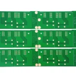
Panel design therefore decides much of the quality of the separation. Panelization practice covers the layout of break lines and tabs, and the rules that matter most here are the distance from the break line to the nearest component, the orientation of the tab relative to the fibre weave and the amount of support the panel receives while it is being separated. Getting those right removes more defects than any machine setting.
Routing Parameters
Routers cut with a rotating bit, and the quality of the cut depends on the bit geometry, the spindle speed, the feed rate and the number of passes. A bit that is fed too fast generates heat and tears the glass fibres rather than cutting them, leaving a ragged edge and a larger burr. Too slow a feed produces heat without progress and wears the bit prematurely. The counter of cuts per bit matters as much as the speed, because a worn bit behaves differently from a new one in ways that are visible only under magnification.
Support during routing is part of the parameter set. A panel that is held only at its edges sags under the cutting force, and the resulting variation in depth changes the stress on the remaining material. Vacuum fixtures and dedicated supports keep the panel flat and repeatable, and a simple first-off inspection under magnification confirms that the setup is producing the edge the design expects. Panel yield analysis usually shows the cost of getting this wrong.
V-Score and Break Methods
V-scoring cuts a groove on both sides of the panel, leaving a controlled web of material that snaps when the panel is flexed. The depth of the score relative to the remaining web decides both the ease of separation and the risk of cracking the laminate. Too shallow and the panel resists until it breaks unpredictably; too deep and the remaining material cracks instead of separating cleanly, sometimes tearing the edge and exposing laminate that should have remained covered.
The break itself should be a controlled operation. Breaking a scored panel by hand introduces an unpredictable force, while a purpose-made breaker applies a bending moment along the score line. Where a fixture is used, the support positions should place the bending stress at the score and nowhere else. The tooling is inexpensive and the difference in edge quality is visible immediately, which makes it one of the easiest improvements to justify. Board edge clearance determines how much room the fixture has to work in.

Burrs, Dust and Cleaning
Both routing and scoring produce debris. Routing produces dust and fibrous particles; scoring and breaking produce small flakes of laminate and, in some cases, fragments of solder mask. The debris lands on the board, in connectors and inside openings, and it is a reliability problem as well as a cosmetic one. Extraction at the cutting head, combined with a cleaning step after separation, is the standard control, and the cleaning method should be compatible with the components already placed.
Burrs along the routed edge are a normal consequence of the cut, and their size depends on the bit condition and the material. A burr that is large enough to interfere with a connector or with a mating surface is a functional defect; a small one is a cosmetic issue that should still be controlled, because it indicates that the bit is approaching the end of its life. Inspecting the edge at a defined interval under magnification gives a trend rather than a snapshot.
Protecting Assemblies During Separation
Where the panel is populated before separation, the operation has to protect components as well as the board. Support under the panel, clearance around tall parts and attention to the direction in which the cut releases stress all reduce the risk. Flexible boards and thin laminates need more support than rigid ones, and the same cutting force that is harmless on a thick panel can flex a thin one far enough to crack a joint.
Components near the break line deserve particular care. A ceramic capacitor standing close to a score line can crack from the flexing that precedes separation, and the crack may not be visible externally or detectable electrically until it fails in the field. Moving the component, changing the tab position or adding a relief cut is a design solution, and it is best applied before the panel is released rather than after the failures start. Edge plating and castellation features add their own constraints to the same area.
Inspection and Verification
Depanelising quality is verified at three levels: the edge, the joints and the immediate surroundings. Edge inspection under magnification confirms the burr size, the laminate condition and the presence of any delamination. Joint inspection, sometimes with an automated optical system and sometimes manually, looks for cracks in the components nearest the break line. A periodic check that includes a bend test or a microsection gives stronger evidence than appearance alone.
Setting one of these checks as a first-off verification after each setup, and as a periodic audit thereafter, catches the slow changes that follow bit wear and fixture movement. Recording the results against the panel design and the machine settings links the inspection back to the parameters, which is what allows a corrective action to be specific rather than a general instruction to be more careful next time.
FAQ
What causes a cracked capacitor near a break line? Flexing during separation. Move the component away from the break line, add support under the panel or change the tab position.
How deep should a v-score be? Deep enough to break cleanly with the specified tooling, shallow enough to leave material that does not crack. Follow the panel supplier’s recommendation and verify on a sample.
How often should router bits be replaced? On a cut counter, with an edge inspection to confirm the interval. Heavy copper and thick panels usually shorten it.
Is hand breaking ever acceptable? For low volumes with the correct technique and tooling it can be, but the result is less repeatable and the edge quality is harder to control.