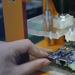
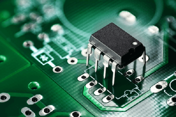
Through-Hole Technology (THT) is a proven method for mounting electronic components onto printed circuit boards (PCBs). Unlike surface mount technology (SMT), THT requires component leads to pass through pre-drilled holes in the PCB and be soldered to pads on the opposite side. This creates a strong mechanical and electrical connection, making through-hole PCB assembly particularly valuable for applications exposed to mechanical stress, vibration, thermal cycling, or high electrical loads.
Although Surface Mount Technology (SMT) has become the dominant assembly method for modern electronics, Through-Hole Technology remains essential for many industrial, automotive, aerospace, power electronics, telecommunications, and high-reliability applications.
As an experienced PCB manufacturer and PCB assembly service provider, Kingda provides professional PCB prototyping, quick-turn PCB manufacturing, through-hole assembly, SMT assembly, mixed-technology PCBA, and full PCB assembly solutions. Our capabilities support customers throughout the product lifecycle, from initial design verification and prototype production to small-batch manufacturing and volume production.
What Is Through-Hole Technology?
Through-Hole Technology (THT) is a PCB assembly technology in which component leads are inserted through holes drilled into a PCB. After insertion, the leads are soldered to copper pads to establish a secure electrical and mechanical connection.
The basic through-hole PCB assembly process typically includes:
- PCB design and DFM review
- PCB fabrication and precision drilling
- Component preparation and insertion
- Wave soldering, selective soldering, or hand soldering
- Cleaning and inspection
- Electrical testing
- Final inspection and packaging
THT components are commonly used for connectors, transformers, relays, switches, large capacitors, inductors, power semiconductors, and other components that require additional mechanical support or higher current-carrying capability.
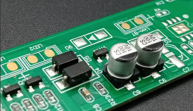
Depending on production volume and product requirements, THT assembly can be performed manually, semi-automatically, or using automated insertion equipment.
Core Advantages of Through-Hole PCB Assembly
1. Excellent Mechanical Strength and Reliability
One of the primary advantages of through-hole assembly is its superior mechanical strength.
Because the component leads pass completely through the PCB, the solder connection is supported by the plated through-hole structure. This provides stronger mechanical retention than many conventional surface-mount connections.
This makes THT particularly suitable for products that experience:
- Mechanical vibration
- Shock and impact
- Repeated connector insertion and removal
- Thermal cycling
- Mechanical stress
- Long-term field operation
Applications such as automotive control systems, industrial equipment, aerospace electronics, power supplies, and communication equipment can benefit significantly from the robust mechanical characteristics of THT components.
At Kingda, component selection, hole design, soldering parameters, and inspection requirements can be evaluated together during the engineering review to improve long-term assembly reliability.
2. Strong Power and Current-Carrying Capability
Through-hole components are widely used in power electronics because their leads and larger package structures can accommodate relatively high current and provide effective thermal paths.
THT is commonly found in:
- Power supplies
- Motor controllers
- Inverters
- Industrial power equipment
- Amplifiers
- Battery management systems
- High-current connectors
- Power distribution circuits
For high-current designs, PCB copper thickness, hole diameter, plating, pad geometry, component lead size, and thermal management must all be considered during PCB design.
Kingda can coordinate PCB fabrication and PCB assembly requirements to ensure that the board design and assembly process are compatible with the intended electrical and thermal performance.
3. Convenient Prototyping, Repair, and Rework
Another advantage of THT is its relative ease of manual inspection, replacement, and repair.
Large through-hole components can generally be accessed more easily than extremely small SMT packages or fine-pitch BGAs. This can simplify:
- Prototype assembly
- Engineering modifications
- Component replacement
- Manual soldering
- Repair and rework
- Low-volume production
For early-stage product development, this flexibility can be particularly useful because designs may undergo multiple engineering revisions before entering mass production.
Kingda supports customers from PCB prototype manufacturing and small-batch PCB assembly to volume production, helping engineering teams transition from prototype validation to stable production.
4. Reliable Performance in Harsh Environments
The mechanical structure of a THT connection can provide excellent resistance to mechanical and thermal stresses.
For products operating under demanding environmental conditions, designers may choose THT components where additional mechanical reinforcement is required.
Typical applications include:
- Automotive electronics
- Industrial automation
- Aerospace systems
- Power electronics
- Railway electronics
- Telecommunications equipment
- Energy systems
However, environmental reliability depends on the complete PCB design and manufacturing process rather than the mounting technology alone. Materials, solder alloy, PCB construction, component qualification, thermal cycling, vibration, and inspection standards should all be evaluated.
5. Suitable for Large and Heavy Components
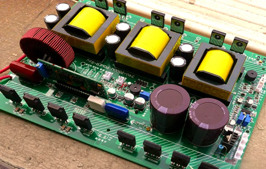
Large components can place considerable mechanical stress on a PCB.
Examples include:
- Large electrolytic capacitors
- Transformers
- Power inductors
- Relays
- Terminal blocks
- Heavy connectors
- Large switches
- Power semiconductor packages
For these components, THT PCB assembly can provide stronger mechanical retention and better resistance to component movement during transportation, vibration, and operation.
Through-Hole PCB Assembly Process
A professional through-hole PCB assembly process requires close coordination between PCB design, fabrication, component preparation, insertion, soldering, inspection, and testing.
Step 1: PCB Design and DFM Review
Before manufacturing begins, engineers review the PCB design and assembly data.
Important factors include:
- Component location
- Hole diameter
- Pad size
- Hole-to-hole spacing
- Component lead dimensions
- Copper thickness
- Plated through-hole structure
- Soldering accessibility
- PCB edge clearance
- Component height
- Thermal requirements
A proper Design for Manufacturing (DFM) and Design for Assembly (DFA) review can identify potential problems before production begins.
For mixed-technology boards, engineers must also determine which components will be assembled using SMT and which require THT.
Step 2: PCB Fabrication and Precision Drilling
The PCB manufacturer creates the required drilled holes based on the engineering data.
For plated through-holes, the hole walls are copper-plated to establish electrical connections between the component lead and the PCB’s copper circuitry.
Hole diameter must provide sufficient clearance for component insertion while maintaining appropriate soldering performance.
The correct hole size depends on:
- Component lead diameter
- Lead shape
- PCB thickness
- Plating thickness
- Assembly method
- Soldering process
Rather than relying on a fixed clearance for every design, Kingda’s engineering team can evaluate the actual component and PCB specifications to determine an appropriate manufacturing approach.
Step 3: Component Insertion
THT components can be inserted manually or automatically.
Manual Component Insertion
Manual insertion is commonly used for:
- Prototypes
- Engineering samples
- Small-batch production
- Complex assemblies
- Low-volume products
- Components with unusual shapes
Operators insert components according to the BOM, assembly drawings, and PCB reference designators.
Automatic Component Insertion
For higher-volume production, automated insertion equipment can improve production efficiency and consistency.
Automatic insertion is particularly suitable for standardized axial and radial components.
The selection between manual and automated insertion depends on:
- Production volume
- Component package
- Board complexity
- Lead configuration
- Product cost target
- Required production speed
Step 4: THT Soldering
After component insertion, the leads must be soldered to establish reliable electrical and mechanical connections.
The main through-hole soldering methods include wave soldering, selective soldering, and manual soldering.
Wave Soldering
Wave soldering is widely used for boards containing a significant number of through-hole components.
The PCB travels over a controlled wave of molten solder. The solder contacts exposed component leads on the bottom side and fills the plated through-holes.
Wave soldering is particularly effective for:
- Medium- and high-volume production
- Boards with many THT components
- Standard through-hole component layouts
- Cost-sensitive production
Selective Soldering
Selective soldering uses a programmable solder nozzle to solder specific through-hole joints individually.
It is especially useful for mixed SMT and THT PCB assembly, where SMT components have already passed through reflow soldering.
Selective soldering offers several advantages:
- Precise solder application
- Reduced thermal exposure
- Programmable solder locations
- Reduced risk to nearby SMT components
- High repeatability
- Suitable for complex mixed-technology boards
Hand Soldering
Manual soldering remains useful for:
- Prototypes
- Low-volume assembly
- Engineering modifications
- Repair and rework
- Heat-sensitive components
- Difficult-to-access components
For high-reliability products, manual soldering should still follow controlled work instructions and applicable workmanship standards.
Through-Hole vs. Surface Mount Technology
Both THT and SMT have important roles in modern electronics manufacturing.
| Characteristic | Through-Hole Technology (THT) | Surface Mount Technology (SMT) |
|---|---|---|
| Mechanical strength | High | Moderate to high depending on package |
| Component size | Generally larger | Very small to large |
| Assembly density | Lower | Higher |
| Automation | Available | Highly automated |
| Power applications | Excellent for many applications | Excellent with suitable packages |
| Prototyping | Convenient | Requires specialized equipment |
| Repair | Generally easier | More challenging for fine-pitch devices |
| Double-sided assembly | More limited | Highly suitable |
| High-frequency applications | Design-dependent | Often advantageous |
| Production cost | Can be higher for some designs | Generally efficient at high volume |
| Typical applications | Connectors, relays, transformers, power components | ICs, processors, memory, passive components |
In many modern products, the best solution is not choosing THT or SMT exclusively.
Instead, manufacturers use mixed-technology PCB assembly, combining SMT and THT components according to electrical, mechanical, thermal, and reliability requirements.
Common Through-Hole PCB Assembly Issues and Solutions
1. Incomplete Solder Fill
Incomplete solder fill occurs when molten solder does not adequately penetrate the plated through-hole.
Possible causes include:
- Incorrect soldering temperature
- Insufficient contact time
- Improper hole-to-lead clearance
- Poor flux activation
- PCB design limitations
- Inadequate preheating
- Component geometry
Solutions
Manufacturers can optimize:
- Solder temperature
- Conveyor speed
- Preheat profile
- Flux application
- Hole diameter
- Component lead preparation
- PCB thermal balance
The appropriate process window should be determined based on the solder alloy, PCB construction, component requirements, and applicable workmanship criteria rather than relying on a single universal temperature setting.
2. Component Insertion Problems
Components may be difficult to insert when the hole pattern or component leads are not properly matched.
Common causes include:
- Incorrect hole diameter
- Drilling deviation
- Bent leads
- Incorrect component dimensions
- Improper lead forming
- Inaccurate insertion equipment
Solutions
A professional assembly process should include:
- Component dimensional verification
- PCB drilling inspection
- First-article assembly
- Insertion equipment calibration
- Lead-forming verification
- DFM/DFA review
Kingda can review component and PCB data before production to identify potential insertion problems at an early stage.
3. Solder Bridging and Excessive Solder
Solder bridging occurs when solder unintentionally connects adjacent pads or leads.
Possible causes include:
- Excessive solder
- Improper flux application
- Incorrect wave height
- Poor PCB layout
- Insufficient component spacing
- Incorrect soldering parameters
Solutions
Potential corrective actions include:
- Optimizing solder wave parameters
- Adjusting flux quantity
- Improving PCB pad and spacing design
- Using appropriate soldering fixtures
- Optimizing component orientation
- Applying selective soldering where appropriate
4. Component Misalignment
Components can shift during insertion or soldering.
This is especially important for:
- Heavy components
- Tall components
- Large connectors
- Transformers
- Relays
- Large capacitors
Solutions
Manufacturers can use:
- Proper lead forming
- Component fixtures
- Temporary adhesive where appropriate
- Optimized conveyor support
- Controlled soldering parameters
- In-process visual inspection
5. Thermal Damage to Components
Some components are sensitive to excessive thermal exposure.
Potential causes include:
- Excessive soldering temperature
- Excessive dwell time
- Improper soldering sequence
- Insufficient thermal protection
Solutions
Depending on the application, manufacturers may:
- Control soldering temperature
- Reduce exposure time
- Use selective soldering
- Use local thermal protection
- Modify soldering sequence
- Follow component manufacturer’s thermal specifications
Cleaning and Inspection of THT Assemblies
After soldering, the assembled PCB may require cleaning depending on the solder paste or flux chemistry and the product’s reliability requirements.
Cleaning can remove:
- Flux residues
- Ionic contaminants
- Process residues
- Dust and foreign materials
For assemblies intended for conformal coating or harsh environments, cleaning requirements may be particularly important.
Inspection Methods
A professional PCB assembly manufacturer may use several inspection techniques:
- Visual inspection
- Automated Optical Inspection (AOI)
- Solder Paste Inspection (SPI) for SMT stages
- X-ray inspection
- Dimensional inspection
- Electrical testing
- Functional testing
For mixed-technology boards, inspection strategies should be determined based on component type, solder joint accessibility, product risk, and customer requirements.
Electrical Testing for Through-Hole PCB Assembly
Inspection confirms workmanship, but electrical testing verifies whether the assembled PCB performs correctly.
Common testing methods include:
In-Circuit Testing (ICT)
ICT uses a fixture with multiple test probes to verify electrical characteristics such as:
- Shorts
- Opens
- Component values
- Circuit continuity
- Selected electrical parameters
ICT is generally more suitable for stable, higher-volume products where fixture costs can be amortized over production quantities.
Flying Probe Testing
Flying Probe Testing (FPT) uses programmable probes to contact test points without requiring a dedicated bed-of-nails fixture.
It is well suited to:
- PCB prototypes
- Engineering samples
- Small-batch PCB assembly
- Frequently revised designs
- Low-volume production
Functional Testing
Functional testing powers the assembled PCB and verifies whether the product performs its intended functions.
Depending on the application, testing may include:
- Voltage output
- Current consumption
- Communication interfaces
- Sensor response
- Relay operation
- Motor control
- Display operation
- Signal integrity
Kingda can work with customers to define an appropriate testing strategy based on product specifications and production volume.
Future Trends in Through-Hole PCB Assembly
Although SMT continues to dominate high-density electronic products, THT remains important and continues to evolve.
1. Selective Soldering Automation
Selective soldering is becoming increasingly important for mixed SMT/THT assemblies because it provides precise soldering while reducing unnecessary thermal exposure.
2. Greater Automation
Automated component insertion, machine vision, AOI, process monitoring, and digital production tracking are improving THT manufacturing efficiency.
3. Higher Reliability Requirements
Automotive, aerospace, industrial, medical, and energy applications continue to demand stronger process control, traceability, and inspection.
4. Mixed-Technology Assembly
Many modern products combine:
SMT + THT + Selective Soldering + Automated Inspection + Functional Testing
This allows designers to select the most appropriate assembly technology for each component rather than forcing the entire board into one manufacturing process.
Why Choose Kingda for Through-Hole PCB Assembly?
As an experienced PCB manufacturer and PCB assembly service provider, Kingda provides integrated manufacturing support from PCB fabrication to finished PCBA.
Our capabilities are designed to support customers at different stages of product development.
1. PCB Manufacturing and Assembly Integration
Kingda can support both PCB manufacturing and PCB assembly, reducing communication gaps between fabrication and assembly.
This helps improve:
- Manufacturing consistency
- Engineering communication
- Production coordination
- Quality traceability
- Lead-time management
2. Prototype to Volume Production
Kingda supports a flexible production model covering:
PCB Prototype → Quick-Turn PCB → Small-Batch PCBA → Medium-Volume Production → Mass Production
This allows customers to maintain manufacturing continuity as their products move from engineering validation into commercial production.
3. SMT + THT Mixed Assembly
For products requiring both surface-mount and through-hole components, Kingda can provide mixed-technology PCB assembly, integrating SMT placement with THT insertion and selective or manual soldering.
4. DFM and Engineering Support
Kingda’s engineering team can review manufacturing data before production and identify potential issues involving:
- Component footprints
- Hole dimensions
- Pad geometry
- Component spacing
- Soldering accessibility
- Assembly orientation
- PCB fabrication compatibility
- Test-point design
This DFM/DFA engineering review helps reduce manufacturing risks before boards enter production.
5. Quality Control and Inspection
Kingda applies structured quality-control procedures throughout the manufacturing process, including appropriate inspection and testing based on project requirements.
Depending on the product, available quality processes may include:
- Incoming component inspection
- SPI
- AOI
- X-ray inspection
- Visual inspection
- ICT
- Flying probe testing
- Functional testing
- Final inspection
- Traceability management
6. Customized PCB Assembly Solutions
Different electronic products have different requirements. Kingda can develop an assembly process according to:
- PCB structure
- Component types
- Production volume
- Reliability requirements
- Industry requirements
- Testing requirements
- Packaging requirements
This makes Kingda suitable for customers requiring a custom PCB assembly solution rather than a standardized production service.
PCB Assembly Process: From Prototype to Production
A reliable THT assembly process is more than simply inserting components and applying solder. It requires coordination across PCB design, component sourcing, PCB fabrication, component insertion, soldering, inspection, testing, and final quality control.
The overall manufacturing workflow can be summarized as:
PCB Design → DFM/DFA Review → PCB Fabrication → Component Sourcing → THT/SMT Assembly → Soldering → AOI/X-Ray Inspection → Electrical Testing → Final Inspection → Packaging → Shipment
With its integrated PCB manufacturing and PCB assembly capabilities, Kingda provides professional solutions for customers ranging from prototype PCB assembly and quick-turn production to small-batch and high-volume manufacturing.
By combining engineering support, controlled manufacturing processes, inspection, testing, and production traceability, Kingda helps customers reduce manufacturing risks, improve product reliability, and accelerate the transition from prototype to mass production.
Conclusion
Through-Hole Technology (THT) remains an important PCB assembly technology despite the widespread adoption of SMT. Its strong mechanical connections, suitability for large and high-power components, and convenient repair characteristics make it particularly valuable in demanding electronic applications.
For modern products, the most effective solution is often a combination of SMT and THT PCB assembly. SMT provides high component density and automation, while THT provides mechanical robustness and reliable mounting for larger or higher-stress components.
As a professional PCB manufacturer and PCB assembly service provider, Kingda provides integrated solutions covering PCB prototype manufacturing, quick-turn PCB production, SMT assembly, through-hole assembly, mixed-technology PCBA, inspection, testing, and volume manufacturing.
Whether you are developing a prototype, preparing a small-batch production run, or scaling an established product to mass production, Kingda can provide engineering and manufacturing support throughout the entire PCB assembly lifecycle.