FR4 vs Rogers PCB for RF Modules: Choosing a Laminate
A radio circuit at two gigahertz can survive on ordinary laminate. The same circuit at twenty-four gigahertz cannot, and the reason is not the schematic but the material the traces are printed on. Choosing between a standard FR4 and a high frequency laminate is the first decision in an RF module design, and it determines the loss budget, the achievable impedance tolerance and a large part of the manufacturing cost.
What Separates the Two
The difference is captured by the dissipation factor, the fraction of the signal energy the dielectric absorbs as heat. Standard FR4 sits in the range of 0.018 to 0.025, a high speed FR4 variant improves that to roughly 0.010 to 0.015, and high frequency materials reach 0.002 to 0.004. Even a modest reduction matters, because dielectric loss scales with frequency and the loss compounds along the whole channel.
The second difference is stability rather than magnitude. A high frequency laminate holds its dielectric constant steady across temperature and frequency, so an impedance designed for 50 ohms stays close to 50 ohms in a cold start and in a hot soak. FR4 varies more, which shifts the impedance of a controlled line and detunes an antenna as the module warms up.
Frequency Ranges in Practice
Below about two gigahertz, and where the trace lengths are short, FR4 is entirely adequate. Sub-gigahertz telemetry, LoRa and other narrowband links at 433, 868 or 915 MHz, Zigbee and Bluetooth modules all design comfortably on standard laminate, and the cost advantage is substantial.
Above 2.4 gigahertz the picture changes. Wi-Fi at 2.4 and 5 GHz, high precision positioning receivers, automotive radar at 24 and 77 GHz, 5G millimeter wave bands and satellite links all depend on the antenna and feed performing close to simulation. At those frequencies the loss of FR4 absorbs a meaningful share of the transmitted power, the impedance drifts with temperature, and the antenna efficiency suffers directly. The routing practice that supports those designs is described in microstrip and stripline routing.
Impedance Control and Antenna Performance
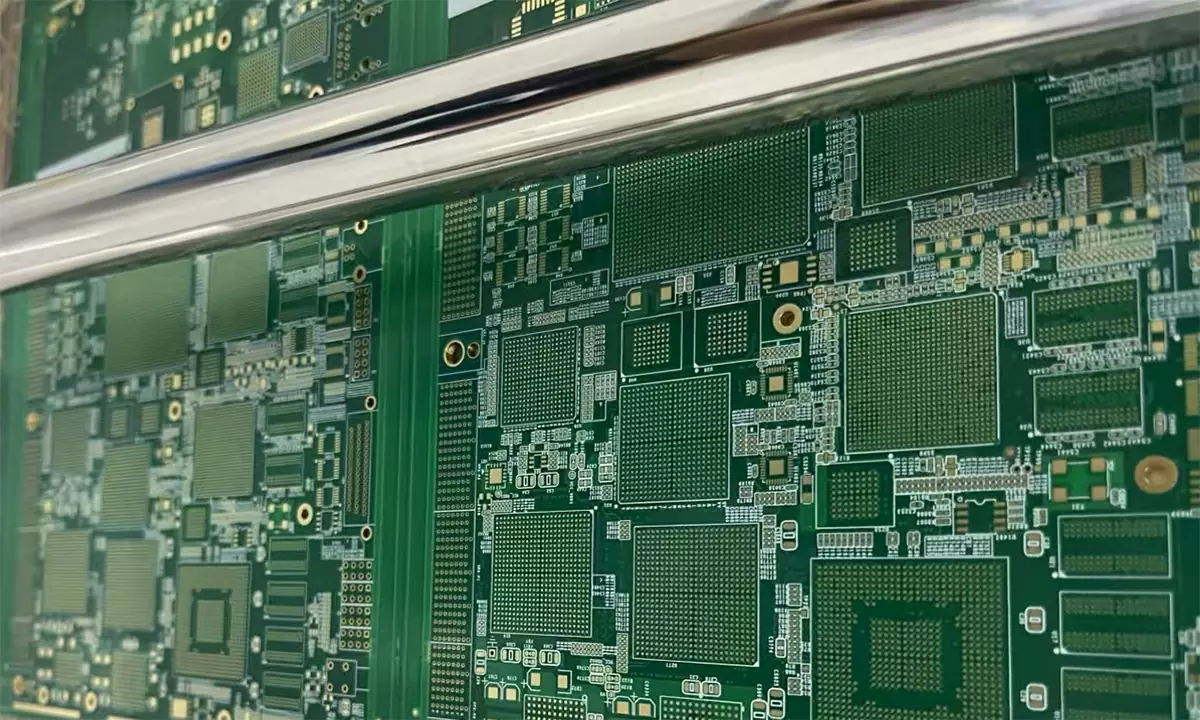
An RF module is built around a controlled impedance, usually a single ended fifty ohm line for the feed and a differential pair at ninety or one hundred ohms where a digital interface shares the board. On FR4 that impedance can typically be held to within about ten percent, and on a high frequency laminate to within five percent, largely because the material properties themselves are more stable.
Antenna efficiency is where the material choice becomes visible in the product specification. A printed antenna on a lossy substrate radiates less of the power delivered to it, which reduces range, raises the power needed for a given link and degrades receiver sensitivity. The effect is small at low frequency and grows quickly, which is why the same antenna geometry that works well at 900 MHz may lose a significant fraction of its efficiency when it is reproduced at 5 GHz on the same laminate. The wider question of low loss routing is covered in high frequency trace routing.
Cost Reality
High frequency laminate costs several times more than FR4 per unit area, and the gap widens when the processing is counted, because the material is softer, more sensitive to moisture and harder to register. A four layer RF board in a high frequency material can easily cost three to eight times its FR4 equivalent, which is why an all high frequency build is reserved for designs that genuinely need it.
The availability question also matters. High frequency laminates are produced by fewer suppliers, are stocked in narrower widths and carry longer lead times, so a design that depends on a single grade without an approved equivalent carries a supply risk as well as a cost premium.
Hybrid Stackups
Most modern RF products do not choose one material or the other. They use a hybrid stackup in which the high frequency material appears only where the radio needs it, usually the outer layers that carry the feed line and the antenna, while the inner layers that carry digital signals, control lines and power are built from ordinary laminate. The radio sees a low loss surface with a stable dielectric, and the rest of the board sees an economical one.
The saving is typically thirty to fifty percent of the material cost, which is why the approach dominates in Wi-Fi modules, 5G equipment and automotive radar. The penalty is manufacturing complexity: two materials with different coefficients of thermal expansion have to be laminated together without warping, and the layer sequence has to be planned so that the expansion is balanced. The principles are those of any mixed stackup, as described in layer stackup planning.
Reliability in Harsh Environments
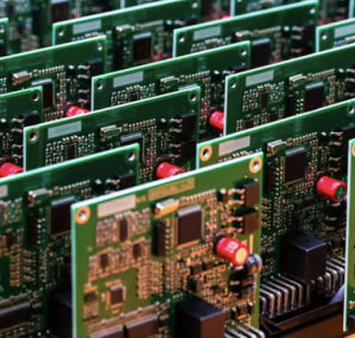
Thermal behaviour is the second reason RF designs move away from FR4, and it applies even where the loss budget would tolerate standard laminate. High frequency materials generally have a lower coefficient of thermal expansion, better dimensional stability and better resistance to thermal cycling. A power amplifier running warm on a board that expands significantly will work its solder joints and shift its impedance as it heats, and both effects are reduced when the laminate is more stable.
That is why automotive radar, outdoor wireless equipment and aerospace systems specify high frequency laminate even where the frequency alone might not demand it. The material is chosen for the environment as much as for the electrical performance, and the reliability requirement is often the decisive argument.
Selection Checklist
Start with the operating frequency and the loss budget, then check whether the antenna is printed on the board. A design that radiates from a printed structure is far more sensitive to laminate loss than one that drives an external antenna through a connector, because the antenna efficiency appears directly in the link budget.
Check the impedance tolerance the design can tolerate, the temperature range the module must hold its performance over, and the cost target. Where the frequency is under two gigahertz and the environment is benign, FR4 is the correct engineering answer and the money is better spent on the layout. Where any of those conditions fails, move to a high frequency material, and consider whether a hybrid stackup gives the performance without paying for the whole board.
FAQ
Can FR4 be used at 2.4 GHz? It can, for short, non critical links. Where the antenna is printed on the board or the link budget is tight, a high frequency laminate gives measurably better range and a more stable match over temperature.
Is a high frequency laminate needed for the whole board? Usually not. A hybrid stackup places the low loss material only in the layers that carry the radio, and builds the digital and power layers from ordinary laminate at a fraction of the cost.
What is the most important material parameter for an RF module? The dissipation factor, because it sets the dielectric loss, followed by the stability of the dielectric constant with temperature and frequency, which sets how well the impedance and the antenna hold their tuning.
Why does a high frequency laminate cost so much more? The chemistry is more specialised, the material is produced in smaller volumes and narrower widths, and processing is less forgiving, so both the material price and the yield loss are higher than for FR4.