Glass Core PCB versus Metal Core PCB: How to Choose
Two board constructions are used when an ordinary laminate cannot carry the heat or hold the dimensions demanded by the application. A metal core PCB puts an aluminium or copper base under an organic dielectric, while a glass core PCB uses a glass substrate with thin copper. They solve overlapping problems in different ways, and choosing wrongly is expensive because both are costly to build.
What Each Construction Is
A metal core board uses a metal plate as the base, with a thin thermally conductive dielectric laminated to it and the circuit formed on top. The metal provides mechanical stiffness and spreads heat laterally, and the dielectric provides the isolation.
A glass core board uses a glass panel as the substrate, with fine copper conductors built on one or both faces using processes borrowed from display and semiconductor manufacturing. The glass provides dimensional stability and very low loss, and its surface is flat enough for the finest geometries.
The Thermal Path
In a metal core board the heat has to cross the dielectric, which is the dominant resistance in the stack even when a thermally loaded material is used. The metal beneath then spreads the heat and conducts it to a heat sink or to the chassis.
A glass core board does not spread heat laterally in the same way, because glass is a poor conductor. Its thermal advantage is dimensional and electrical rather than thermal, and heat is usually removed through vias to the opposite side. A metal core PCB is therefore the better answer when the requirement is to move a large amount of heat away from a few devices, and the special materials discussed for a trace width and current calculation apply when sizing the conductors that feed them.

Expansion and Dimensional Stability
Glass has a low coefficient of thermal expansion and, more importantly, it does not absorb moisture or soften at reflow temperatures. The dimensional change through the assembly process is very small, which is why glass is attractive for applications with the finest pitch and the tightest registration.
A metal core board expands with the metal, and the dielectric constrains it only partly, so the assembly changes dimension through reflow. For a board carrying an area array package with a fine pitch, that movement adds to the placement tolerance, and the wider effects, including panel warpage after reflow, are described in the material on dimensional stability and expansion. Metal also conducts heat into the board from the chassis, which can be undesirable where the electronics generate little heat.

Signal Integrity and Loss
Glass has excellent dielectric properties with low loss, and its stability with frequency and temperature makes it attractive for high speed channels. The very flat surface also allows smooth copper, which reduces conductor loss at high frequency.
A metal core board’s dielectric is loaded with ceramic filler to conduct heat, and that filling tends to raise the dielectric loss. For a power converter this is irrelevant, while for a high speed differential link it can consume a significant part of the margin. Choosing between them on signal grounds follows the reasoning in multilayer PCB advantages for high speed.
Mechanical Behaviour
A metal core board is stiff and robust, and it tolerates handling and clamping well. It can be machined, tapped and formed, which allows it to serve as a structural part of the assembly as well as a circuit carrier.
Glass is brittle. It cracks under point loads and at edges, so mounting has to distribute the clamping force and the panel has to be handled as a component. That brittleness is the main reason glass core boards remain confined to applications where the electrical or dimensional benefit justifies the care they require.
Manufacturing Differences
Metal core boards are built on processes that resemble conventional board fabrication, with the additional steps of laminating the dielectric to the metal and machining the outline. Drilling through aluminium requires different parameters, and the burr that forms must be removed.
Glass core manufacturing borrows from display panel production: large panels, thin film deposition, photolithography and fine line plating on a substrate that cannot be handled like a laminate. The equipment base is different from a conventional board shop, which is why the supply chain is small.
Where Each Is Used
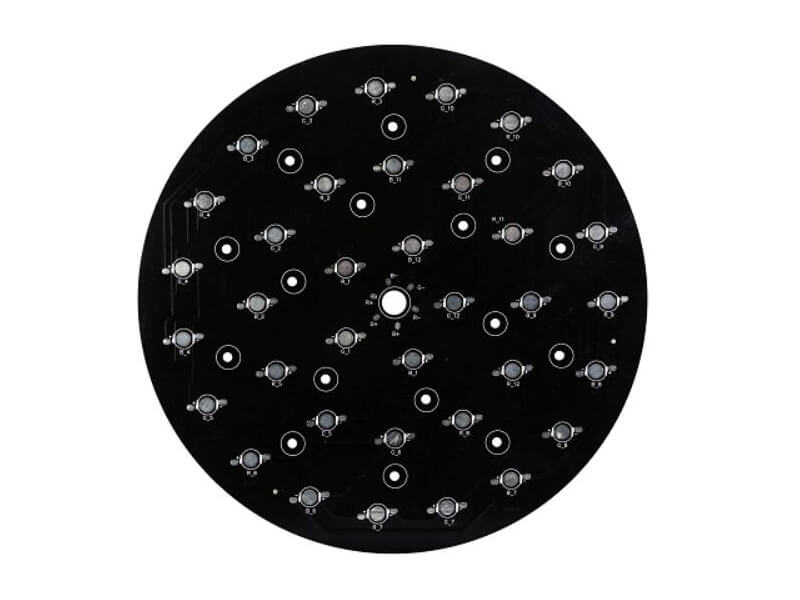
Metal core boards appear in LED lighting, power converters, motor drives and automotive lighting, wherever a handful of devices dissipate significant power into a confined space. The construction is mature and well supported.
Glass core boards appear in high performance computing packages, in radio frequency modules where the loss budget is tight, and in applications where the pitch is fine enough that laminate dimensional stability is the limiting factor. The technology is newer and the cost is higher, and it is chosen when nothing else meets the requirement. The decision is worth revisiting at each design revision rather than being fixed once, because both technologies are still developing and the supply base for fine pitch glass work continues to widen.
Cost and Availability
A metal core board costs more than FR4, mostly because of the dielectric and the machining, but it is available from a broad supply base and the pricing is well understood. Prototype and volume pricing both scale with area and with the thermal performance of the dielectric.
A glass core PCB is far more expensive, with most of the cost in the substrate and the fine line processing, and the number of suppliers is small. The cost is justified by the electrical performance and the dimensional precision rather than by the thermal path, and a design that needs only thermal performance should not be paying for glass.
Making the Choice
Ask what the limiting requirement is. Where heat has to leave a few devices quickly and the board can be bolted to a heat sink, a metal core board is the answer. Where the limit is registration, flatness, loss or dielectric stability at the finest pitch, glass core is the candidate.
Where the requirement is moderate in both directions, neither is necessary, and a conventional laminate with thermal vias and a good stackup will be cheaper and adequate. The engineering effort is better spent on getting the stackup right than on specifying a technology the design does not need, as the general guidance in layer stackup from one to eight layers makes clear. A conventional multilayer board with a well designed thermal via array will solve most heat problems at a fraction of the cost of either specialist construction, and it leaves room to change the design later without requalifying the material.
FAQ
Is a glass core PCB a better thermal conductor than a metal core PCB? No. Glass conducts heat poorly. Its advantages are dimensional stability, flatness and low dielectric loss, with heat removed through vias.
Can a metal core board carry high speed signals? It can, but the filled dielectric has higher loss than a dedicated high frequency laminate. Where the link budget is tight, another construction is preferable.
Why is glass core so expensive? The substrate, the fine line processing and the small supplier base. Most of the cost is in the panel rather than in the assembly steps.