As electronic devices continue to become smaller, lighter, and more powerful, HDI PCB technology has become an increasingly important solution for modern electronics design. Wearable devices, smartphones, industrial IoT equipment, medical electronics, automotive systems, communication equipment, and high-performance computing platforms all require greater circuit density within increasingly limited board space.
Unlike conventional multilayer PCBs, High-Density Interconnect (HDI) PCBs use fine lines, smaller pads, microvias, blind vias, buried vias, and sequential lamination structures to create more efficient electrical interconnections.
However, successful HDI PCB design is not simply a matter of making traces and vias smaller. Designers must balance signal integrity, power integrity, thermal management, manufacturability, reliability, cost, and production capability.
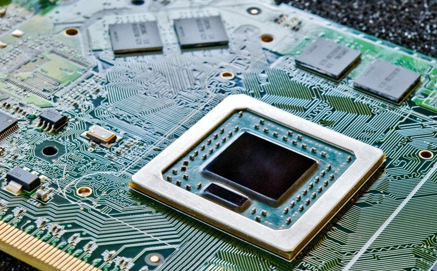
A well-designed HDI PCB should not only meet the electrical requirements of the circuit but also be realistic for the selected PCB manufacturer’s process window.
Kingda specializes in advanced PCB manufacturing, including HDI PCB, multilayer PCB, blind/buried via PCB, controlled-impedance PCB, high-frequency PCB, and high-Tg PCB technologies. Its published HDI capabilities include laser microvias down to 75 μm in advanced production, stacked microvias, copper-filled microvias, buried filled vias, and buildup structures up to 5+N+5 under advanced capability specifications. (Kingda)
What Is HDI PCB Technology?
HDI PCB stands for High-Density Interconnect Printed Circuit Board. It is a PCB technology designed to provide higher wiring density within a given board area than conventional PCB construction.
The higher density is achieved through a combination of:
- Fine line and space
- Microvias
- Blind vias
- Buried vias
- Smaller capture pads
- Sequential lamination
- High-density component breakout
- Advanced multilayer stackups
One of the most important characteristics of HDI is that interconnections do not always have to travel through the entire PCB.
A conventional through-hole via may pass from the top layer to the bottom layer, occupying routing space across multiple layers. In contrast, a microvia can connect only the layers that require electrical connectivity.
This enables designers to create shorter connections and reserve more routing channels for high-density circuitry.
Typical HDI Features
Depending on the manufacturing process and HDI class, designers may encounter:
- Line/space around 75 μm / 75 μm or finer
- Laser-drilled microvias
- Capture pads around 0.20–0.25 mm
- Stacked or staggered microvias
- Copper-filled microvias
- Sequential buildup layers
- Blind and buried vias
These values are not universal HDI design rules. The actual minimum feature size depends on the PCB manufacturer, material system, copper thickness, layer structure, fabrication method, and reliability requirements.
For example, Kingda currently publishes standard HDI microvia capability down to 100 μm and advanced capability down to 75 μm, with capture pads down to 0.20 mm in advanced production. (Kingda)
The Three Main Via Structures in HDI PCB Design
Understanding the different via structures is fundamental to successful HDI PCB design.
Blind Vias
A blind via connects an outer layer to one or more inner layers without extending through the entire PCB.
Blind vias are particularly useful for:
- BGA breakout
- Fine-pitch ICs
- High-density routing
- Saving inner-layer routing space
For example, a microvia from Layer 1 to Layer 2 can provide a direct escape route from a fine-pitch BGA without creating a through-hole structure across the entire stackup.
Buried Vias
A buried via connects internal PCB layers without being exposed on the top or bottom surface.
Because the via is created within the internal structure, it can provide additional routing flexibility without consuming valuable outer-layer space.
However, buried-via structures generally involve additional fabrication processes and should therefore be specified only when their electrical or routing benefits justify the added manufacturing complexity.
Microvias
Microvias are small laser-drilled vias commonly used in HDI construction.
They can be configured as:
Staggered Microvias
Adjacent microvias are horizontally offset. This construction is generally easier to manufacture and can reduce some of the process challenges associated with stacking.
Stacked Microvias
Microvias are positioned directly above one another across buildup layers.
Stacked microvias provide excellent routing efficiency, but they require tighter process control. Depending on the structure, copper filling and planarization may be required.
Kingda’s published HDI capabilities include stacked microvias, copper-filled microvias, and buried filled vias, supporting more advanced HDI architectures. (Kingda)
HDI PCB Design Rules and Typical Parameters
There is no single universal set of HDI design rules because the manufacturable limits depend heavily on the PCB fabrication process.
A practical comparison is:
| Parameter | Conventional Multilayer PCB | HDI PCB | Advanced HDI |
|---|---|---|---|
| Typical Line/Space | ≥0.10/0.10 mm | ~0.075/0.075 mm | ~0.050/0.050 mm or finer |
| Mechanical Via | ~0.20–0.30 mm+ | Smaller structures possible | Laser microvia structures |
| Microvia | Not normally required | ~0.10 mm | ~0.075 mm or smaller |
| Capture Pad | Larger | Reduced | Very small |
| Via Structure | Through-hole | Blind/microvia | Stacked/staggered |
| Lamination | Conventional multilayer | Sequential buildup | Multiple buildup cycles |
| Routing Density | Moderate | High | Very high |
These values should be treated as engineering references rather than guaranteed manufacturing limits.
Before beginning detailed layout, designers should obtain the fabricator’s current HDI PCB design rules.
Signal Integrity Considerations for HDI PCBs
Higher routing density does not automatically mean better electrical performance.
As signal speeds increase, the physical geometry of the transmission path becomes increasingly important.
Via Stubs
A via that extends beyond the layer where a high-speed signal terminates can create a via stub.
At sufficiently high frequencies, the stub can introduce:
- Impedance discontinuity
- Reflections
- Resonance
- Increased insertion loss
- Signal distortion
Using blind vias, buried vias, microvias, or back-drilling, depending on the architecture, can help control unwanted via structures.
The correct solution depends on the signal frequency, rise time, stackup, via geometry, and system requirements.
Impedance Control
High-speed signals require controlled transmission-line geometry.
Important parameters include:
- Trace width
- Trace thickness
- Dielectric thickness
- Dielectric constant
- Reference-plane distance
- Copper roughness
A designer should establish the target impedance before routing.
Common targets include 50 Ω single-ended and 90–100 Ω differential, depending on the interface and system specification.
Kingda provides controlled-impedance PCB manufacturing and publishes impedance-related capabilities as part of its PCB manufacturing services. (Kingda)
Crosstalk
HDI routing creates greater opportunities for coupling because conductors are placed closer together.
To control crosstalk:
Keep critical traces separated where practical.
Minimize long parallel runs.
Use solid reference planes.
Control trace geometry.
Avoid unnecessary layer transitions.
A common starting point is the 3W spacing concept, but actual spacing should be established using field-solver or SI analysis when performance requirements are demanding.
Return Path Management
A high-speed signal does not exist independently of its return current.
Designers should:
- Maintain continuous reference planes
- Avoid routing across plane splits
- Keep high-speed signals close to their reference plane
- Provide appropriate return paths at layer transitions
- Minimize discontinuities around vias
Kingda also emphasizes continuous ground planes, controlled impedance, short signal paths, and minimizing unnecessary vias as important practices for high-speed and EMI-conscious PCB designs. (Kingda)
Thermal Management in HDI PCB Design
Miniaturization increases power density.
Although HDI primarily solves routing-density challenges, the resulting compact layout can make thermal management more difficult.
Common approaches include:
Thermal Vias
Thermal vias provide conductive paths from a component pad to an internal or bottom copper structure.
They are commonly used below:
- Power ICs
- MOSFETs
- Regulators
- LED components
- High-power processors
Copper Structures
Increasing copper thickness or using larger copper areas can improve heat spreading, although this must be balanced against manufacturability and cost.
Kingda publishes copper capabilities from 1/3 oz to 5 oz under standard specifications and up to 6 oz under advanced specifications, depending on the PCB structure. (Kingda)
Thermal Material Selection
For high-power or thermally sensitive products, material selection becomes important.
Depending on the application, designers may consider:
- High-Tg FR-4
- Low-loss laminates
- Metal-core materials
- High-thermal-conductivity dielectric systems
- Specialized RF materials
How to Design an HDI PCB for Manufacturing
One of the most common causes of HDI prototype failures is the gap between what the designer assumes can be manufactured and what the fabricator’s actual process can reliably produce.
A successful HDI PCB manufacturer should be involved early.
1. Obtain the Manufacturer’s Design Rules First
Before routing, request:
- Minimum line/space
- Minimum laser drill
- Capture pad limits
- Microvia aspect ratio
- Stacked-via requirements
- Copper-fill requirements
- Solder-mask capabilities
- Registration tolerances
- Sequential-lamination limitations
This prevents designing a board around manufacturing parameters that the supplier cannot support.
2. Perform DFM Before Gerber Release
A professional HDI PCB DFM analysis should identify potential:
- Annular-ring violations
- Solder-mask issues
- Insufficient spacing
- Microvia problems
- Unsupported stackups
- Registration risks
- Copper-density problems
Kingda provides engineering support including DFM, DFA, DFX, Gerber review, stackup analysis, BOM verification, and manufacturing documentation review. (Kingda)

3. Develop the Stackup With the Fabricator
The HDI stackup determines much of the board’s electrical and manufacturing performance.
The stackup should consider:
- Core thickness
- Prepreg thickness
- Dielectric constant
- Copper thickness
- Microvia structure
- Reference planes
- Impedance targets
- Sequential buildup
- Thermal requirements
For advanced high-speed products, stackup simulation should be completed before routing begins.
When Should You Choose HDI Instead of a Standard PCB?
HDI PCB is powerful, but it should not automatically replace conventional multilayer PCB technology.
HDI is particularly valuable when:
The BGA Pitch Is Very Small
Fine-pitch BGAs can become extremely difficult to escape using conventional through-hole vias.
Microvias can provide a more efficient breakout solution.
Board Size Is Strictly Limited
If the enclosure size is fixed but the circuit continues to grow, HDI can increase routing density without continuously adding board layers.
Component Density Is Very High
Compact systems such as:
- Wearables
- Smartphones
- Medical devices
- IoT modules
- Automotive electronics
- Cameras
- AI edge devices
can benefit from HDI technology.
High-Speed Performance Requires Reduced Via Structures
When signal integrity analysis demonstrates that conventional through-hole via stubs are creating unacceptable discontinuities, blind/buried vias or microvias can provide a better electrical structure.
HDI vs. Standard Multilayer PCB
| Factor | Standard Multilayer PCB | HDI PCB |
|---|---|---|
| Routing Density | Moderate | High |
| Manufacturing Complexity | Lower | Higher |
| Microvias | Usually unnecessary | Common |
| Fine-Pitch BGA Support | Limited by design | Excellent |
| Board Miniaturization | Moderate | Excellent |
| Manufacturing Cost | Lower | Higher |
| Design Rules | More forgiving | More restrictive |
| Lead Time | Generally shorter | Generally longer |
| Best Application | General electronics | Compact/high-density electronics |
The correct choice should be based on the actual electrical and mechanical requirements rather than simply selecting the most advanced technology.
Common HDI PCB Design Mistakes
Using HDI Without a Real Routing Requirement
HDI adds process complexity and cost.
If a standard multilayer PCB can meet the design requirements, it may remain the more economical solution.
Designing Below the Manufacturer’s Capability
A theoretical design may look excellent in an EDA tool but fail during fabrication.
Always design within the manufacturer’s validated process window.
Ignoring Sequential Lamination
The number of buildup cycles influences:
- Cost
- Yield
- Lead time
- Registration
- Reliability
The layer structure should therefore be discussed before layout.
Improper Microvia Design
Microvia diameter, capture-pad size, aspect ratio, stacking method, filling process, and copper thickness must all be compatible.
Forgetting Thermal Constraints
Increasing circuit density without considering heat concentration can result in a board that routes successfully but performs poorly under real operating conditions.
Kingda HDI PCB Manufacturing Advantages
Kingda provides HDI PCB manufacturing and assembly as part of its integrated PCB/PCBA manufacturing services. Its published capabilities include rigid, multilayer, HDI, high-frequency, high-Tg, heavy-copper, flexible, rigid-flex and controlled-impedance PCB technologies. (Kingda)
Advanced HDI Manufacturing Capability
Kingda publishes:
- 75 μm minimum laser drill under advanced capability
- 50/50 μm minimum inner-layer line/space under advanced capability
- 64/76 μm outer-layer line/space under advanced capability
- 0.20 mm minimum advanced capture pad
- Stacked microvias
- Copper-filled microvias
- Buried filled vias
- Up to 5+N+5 buildup layers under advanced capability
Actual capability depends on board design, materials, stackup, copper thickness, and production requirements. (Kingda)
Engineering Support
Kingda provides engineering assistance throughout the manufacturing process, including:
DFM → DFA → BOM Verification → Gerber Review → Pick-and-Place Verification → Component Availability Analysis → Stackup/Process Optimization. (Kingda)
Prototype to Mass Production
Kingda supports the complete production lifecycle:
Rapid Prototype → Low Volume → Medium Volume → High Volume Production
This allows hardware teams to continue working with the same manufacturing partner when a validated HDI design moves into production. (Kingda)
One-Stop HDI PCB + PCBA
Kingda integrates:
HDI PCB Fabrication + Component Procurement + SMT + THT/DIP + Inspection + Testing + Finished Product Assembly
This reduces supplier handoffs and makes it easier to coordinate complex HDI projects. (Kingda)
Quality Systems
Kingda states that it has IATF 16949, ISO 13485, and ISO 9001 quality-management certifications and serves applications including automotive, medical, industrial automation, AI, communication, and other electronics sectors. (Kingda)
Conclusion
HDI PCB design is ultimately a balance between electrical performance, physical miniaturization, manufacturing capability, cost, and reliability.
The most successful HDI designs do not begin with the smallest possible trace or via. They begin with a realistic manufacturing strategy.
A practical development workflow is:
Designers should work with the HDI PCB manufacturer early, particularly when the project uses stacked microvias, fine line/space, high layer counts, controlled impedance, high-speed interfaces, or special materials.

With published capabilities covering HDI, stacked and copper-filled microvias, fine-line fabrication, multilayer PCB manufacturing, controlled impedance, and PCB assembly, Kingda can support HDI projects from engineering development through production. (Kingda)
For compact, high-density electronic products, the right HDI strategy can reduce board size, improve routing efficiency, simplify component breakout, and create a more scalable path from prototype to volume manufacturing.