Heavy Copper PCB for Industrial Power Supplies: Applications and Selection Guide
Industrial power supplies serve as the power core of many industrial systems. They are expected to provide stable high-power and high-current output over long operating periods while handling challenging conditions such as elevated temperatures, vibration, and mechanical stress.
These demanding operating conditions place strict requirements on PCB current carrying capacity, thermal performance, mechanical strength, and long-term reliability. A Heavy Copper PCB can be an effective solution because its thicker copper layers provide improved current carrying capability and enhanced heat conduction compared with conventional PCB constructions.
Heavy copper boards are widely considered for applications such as industrial power supplies, motor controllers, power converters, welding equipment, inverters, battery systems, and other high-current electronic equipment.
However, selecting the appropriate heavy copper construction requires more than simply choosing the thickest available copper foil. Copper thickness, trace width, thermal management, substrate selection, via construction, surface finish, manufacturing capability, and total cost should all be evaluated according to the actual application.
1. Why Heavy Copper PCBs Are Important for Industrial Power Supplies
The primary advantages of a Heavy Copper Circuit Board in industrial power applications are high current carrying capacity, improved thermal performance, and enhanced mechanical robustness.
High Current Carrying Capacity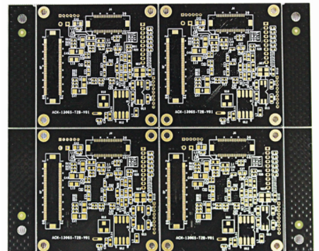
Industrial power supplies may need to handle currents ranging from several amperes to dozens of amperes or even higher, depending on the system architecture.
When conventional copper thickness is insufficient for a high-current circuit, excessive electrical resistance can cause increased heat generation. Under demanding operating conditions, this can contribute to copper overheating, solder joint damage, reduced efficiency, and premature component failure.
A heavy copper construction increases the copper cross-sectional area available for current transmission. This reduces resistance and allows high-current paths to operate more reliably when the PCB layout and thermal design are properly engineered.
For example, in the output stage of an industrial power supply, a heavy copper board can provide a robust current path between the power conversion circuitry and loads such as motors, heaters, actuators, or other high-power equipment.
Improved Thermal Management
Industrial power electronics generate significant heat from switching losses, semiconductor losses, copper resistance, and other sources.
If heat cannot be removed efficiently, the temperature of power components and surrounding PCB areas may rise beyond their recommended operating range. Excessive temperature can shorten component life and negatively affect system stability.
The thicker copper used in a Power PCB can also act as an efficient thermal conduction path. Heat generated around power components can be distributed through the copper structure and transferred toward thermal management structures such as heatsinks or other cooling solutions.
This can help reduce localized hot spots and improve the overall thermal balance of the power supply.
Improved Mechanical Robustness
Industrial equipment may be exposed to vibration, transportation shock, mechanical stress, and repeated thermal cycling.
The additional copper mass and robust construction of a heavy copper board can contribute to mechanical stability. When properly designed and manufactured, the board can better withstand demanding installation and operating conditions while reducing the risk of copper separation or structural deformation.
For projects where PCB fabrication must be coordinated with downstream assembly, integrating manufacturing and assembly can also simplify production management. Gopcba provides PCB Manufacturing services for different PCB structures and application requirements. PCB Manufacturing
2. How to Select the Right Copper Thickness
Copper thickness is one of the most important parameters when selecting a High Current PCB for an industrial power supply.
The appropriate copper thickness should be determined according to the actual current, trace geometry, allowable temperature rise, board structure, and thermal environment rather than simply choosing the maximum copper thickness.
Match Copper Thickness to Current Requirements
As the operating current increases, the required copper cross-sectional area generally needs to increase as well.
For relatively lower-current industrial control power supplies, a moderate increase in copper thickness may be sufficient. For higher-current applications such as inverter power supplies, welding equipment, motor controllers, and high-power converters, significantly thicker copper may be required.
However, copper thickness should always be evaluated together with trace width and temperature rise. Increasing trace width can sometimes provide additional current capacity without requiring an unnecessarily thick copper layer across the entire board.
Use Different Copper Thicknesses Where Appropriate
Not every circuit on an industrial power supply carries the same current.
For example:
- Input power paths may carry relatively high current.
- Rectifier circuits may require increased copper capacity.
- DC output paths may carry substantial continuous current.
- Power semiconductor connections may require enhanced thermal and electrical conduction.
- Control and communication circuits generally carry much lower current.
A practical PCB design can therefore allocate copper according to individual circuit requirements.
Using heavy copper only where necessary can provide a better balance between performance, manufacturability, and cost.
3. Consider Thermal Requirements When Selecting the Substrate
Copper thickness is only one part of the thermal solution. The PCB substrate and overall thermal architecture also play important roles.
FR-4 and High-Temperature Materials
For many industrial applications, FR-4 remains a practical substrate option because of its electrical insulation, mechanical stability, availability, and cost effectiveness.
When the operating temperature or power density increases, the PCB designer should also evaluate the thermal and reliability characteristics of the selected laminate.
Material selection should consider:
- Operating temperature
- Glass transition temperature
- Thermal expansion characteristics
- Electrical insulation requirements
- Mechanical strength
- Long-term reliability
- Compatibility with the required copper thickness
For demanding power applications, specialized high-temperature or thermally optimized materials may be considered when conventional FR-4 cannot provide the required performance.
Metal-Core Options
When thermal requirements are particularly demanding, metal-core PCB structures may provide an alternative.
Aluminum or copper-based substrates can offer improved heat dissipation compared with conventional dielectric constructions. These solutions can be useful for high-power modules where efficient thermal transfer is a major design priority.
However, metal-core solutions can increase manufacturing complexity and overall cost. They should therefore be selected according to actual thermal requirements rather than used simply because they offer higher theoretical thermal performance.
4. Manufacturing Reliability Is Critical
An industrial power supply may be designed for many years of operation. Therefore, the manufacturing quality of the Industrial Power Supply PCB can have a direct impact on the long-term reliability of the complete system.
Several manufacturing factors deserve particular attention.
Layer Bonding
Heavy copper constructions can introduce additional challenges during lamination.
The PCB manufacturer must ensure that copper layers and dielectric materials are properly bonded and that the laminate structure remains stable throughout thermal processing.
Poor lamination control can result in:
- Delamination
- Voids
- Warpage
- Internal stress
- Reduced structural reliability
A suitable manufacturing process should be selected according to the copper thickness, layer structure, laminate type, and overall stack-up.
Surface Finish
The surface finish should be selected according to the electrical, mechanical, environmental, and assembly requirements of the product.
Industrial power supplies may operate in environments containing dust, moisture, vibration, or other contaminants. The selected surface finish should therefore provide appropriate solderability, corrosion resistance, and connection reliability.
Potential options include finishes such as ENIG and immersion tin, depending on the application and assembly process.
Via Reliability
Vias are particularly important in high-current PCB designs because they may carry both electrical current and thermal energy between layers.
Insufficient via copper thickness can create electrical resistance and localized heating. Repeated thermal cycling can also place mechanical stress on plated through-holes.
For heavy copper designs, the manufacturer should verify that the via plating process can provide the required copper thickness and reliability.
For projects requiring components to be mounted after PCB fabrication, the assembly process must also be matched to the board structure. Through-Hole PCB Assembly can be useful for power components and other applications where mechanically robust component connections are required. Through-Hole PCB Assembly
5. Balance Performance and Cost
One of the most common mistakes in heavy copper PCB selection is choosing excessive copper thickness without considering the actual electrical requirements.
Although thicker copper can improve current carrying capacity, it can also increase material and manufacturing costs.
Avoid Over-Specification
For example, if the maximum current of a particular power circuit can be safely handled by a moderate copper thickness combined with sufficiently wide traces, selecting an extremely thick copper layer may provide little additional practical benefit.
Instead, PCB designers can optimize:
- Copper thickness
- Trace width
- Copper distribution
- Thermal vias
- Component placement
- Power-plane structure
- Heat dissipation paths
This approach can achieve the required electrical and thermal performance without unnecessarily increasing manufacturing costs.
Consider Production Volume
Production volume should also influence the sourcing strategy.
For large-volume projects, manufacturers may be able to develop a customized copper thickness and stack-up optimized for the application.
For prototype and low-volume projects, using an established manufacturing process can help control engineering costs and production lead times.
When the board is being developed for engineering validation or early-stage production, Low-Volume PCB Assembly can help support smaller production requirements before moving to larger-scale manufacturing. Low-Volume PCB Assembly
6. PCB Layout Considerations for High-Current Applications
Selecting a suitable High Current PCB material is only part of the solution. PCB layout has a major influence on electrical and thermal performance.
Keep High-Current Paths Short and Wide
High-current traces should generally be designed with sufficient width and appropriate copper thickness.
Long, narrow traces increase resistance and can generate unnecessary heat.
Where possible, high-current paths should be kept short and direct.
Optimize Power Component Placement
Power semiconductor devices, inductors, transformers, capacitors, and other high-power components should be positioned according to the current flow and thermal architecture.
Components generating significant heat should have an effective thermal path to the PCB copper structure and external cooling system.
Use Copper Planes Where Appropriate
Large copper areas can reduce electrical resistance and provide additional thermal spreading.
Power and ground planes can also help distribute current more evenly when properly designed.
However, copper distribution should be carefully evaluated during manufacturing because large copper areas can influence thermal balance during soldering and PCB fabrication.
7. Heavy Copper PCB Applications in Industrial Power Electronics
A Heavy Copper PCB can be used in a wide range of industrial power applications.
Typical applications include:
Industrial Switching Power Supplies
High-power switching supplies often require PCB structures capable of handling substantial current while efficiently managing heat.
Heavy copper construction can support high-current paths between rectification, switching, filtering, and output stages.
Motor Drives and Inverters
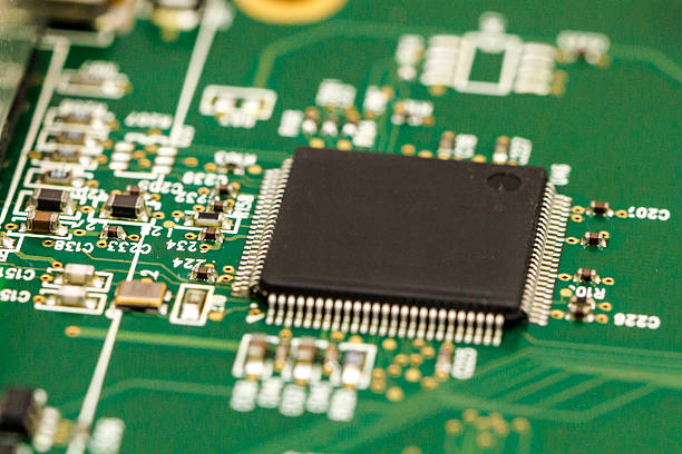
Motor control systems can generate significant current and heat during operation.
Heavy copper boards can provide robust current paths for inverter stages and power switching circuits.
Welding Equipment
Welding power supplies can involve extremely high current levels.
The PCB must therefore be designed with suitable copper thickness, trace geometry, thermal management, and mechanical reliability.
Battery and Energy Storage Systems
Battery management and power conversion systems may also require high-current PCB structures.
Depending on the system architecture, heavy copper can be used for power distribution, charging, discharging, and conversion circuits.
EV Charging and Power Conversion
Charging equipment and power conversion modules frequently require high-current PCB solutions.
Heavy copper can help support the electrical and thermal demands of these systems when combined with an appropriate PCB layout and manufacturing process.
8. Combining PCB Manufacturing and Assembly
For industrial power electronics, the PCB is only one component of the overall manufacturing process. After fabrication, electronic components must be installed, soldered, inspected, and tested.
Depending on the product design, the assembly process may involve SMT, through-hole, or mixed-technology assembly.
For boards containing both surface-mount and through-hole power components, Mixed Technology PCB Assembly can combine SMT and through-hole processes within the same manufacturing workflow. Mixed Technology PCB Assembly
For early-stage products, prototypes can also be assembled in smaller quantities to verify electrical performance, thermal behavior, component placement, and manufacturability before volume production.
This integrated approach can reduce supplier coordination requirements and provide a more streamlined transition from PCB fabrication to assembled electronic products.
9. Key Factors for Selecting a Heavy Copper PCB Supplier
When sourcing a Power PCB for industrial equipment, buyers should evaluate more than the quoted PCB price.
Important factors include:
- Copper thickness capability
- Maximum board thickness
- Layer count capability
- High-current trace manufacturing capability
- Heavy copper via plating
- Lamination capability
- Thermal management experience
- Dimensional control
- Surface finish options
- Electrical testing
- Production volume flexibility
- Assembly capabilities
- Component sourcing capabilities
- Quality management and inspection processes
A supplier with both fabrication and assembly capabilities can be particularly useful when the project requires a complete manufacturing solution.
10. Heavy Copper PCB Selection Checklist
Before placing an order, engineers and purchasing teams can evaluate the following parameters:
| Parameter | Key Consideration |
|---|---|
| Copper thickness | Match with maximum current and allowable temperature rise |
| Trace width | Ensure adequate current carrying capacity |
| Substrate | Select according to temperature and reliability requirements |
| Thermal design | Provide efficient heat dissipation paths |
| Via structure | Verify adequate copper thickness and thermal reliability |
| Surface finish | Match electrical, environmental, and assembly requirements |
| Board stack-up | Optimize power distribution and mechanical stability |
| Production volume | Select a suitable manufacturing strategy |
| Testing | Confirm electrical and structural inspection requirements |
| Assembly | Determine whether SMT, through-hole, or mixed assembly is required |
Conclusion
A Heavy Copper Circuit Board can provide significant advantages for industrial power supplies that require high current carrying capacity, effective heat dissipation, and reliable operation under demanding conditions.
The correct selection should not be based solely on copper thickness. Engineers should evaluate current requirements, trace width, thermal performance, substrate characteristics, via construction, surface finish, manufacturing reliability, production volume, and overall cost.
For high-power applications, an optimized combination of copper thickness, PCB layout, thermal design, and manufacturing process can provide better performance than simply selecting the thickest possible copper.
When PCB fabrication and assembly are coordinated through a capable manufacturing partner, the entire production process can be more efficient and consistent. Gopcba supports PCB manufacturing and PCB assembly requirements ranging from prototypes and low-volume production to more comprehensive manufacturing solutions, helping electronic product developers move from PCB design to reliable finished assemblies.