



Choosing a High-Performance Laminate: Polyimide, Low-Loss and Thermal Grades
Materials chosen for harsh environments are not simply better versions of ordinary laminate. They are different chemistries, each solving one problem well and accepting a penalty elsewhere. A high-performance laminate picked for thermal conductivity is not the same material that solves a millimetre-wave loss budget, and treating the category as a single ladder from cheap to expensive leads to the wrong choice.
The Material Families
Four families cover most of the high-performance range. High-temperature polyimide laminates tolerate continuous operation well above the limits of ordinary epoxy, which suits aerospace, defence and high-power electronics where the ambient is hostile and the thermal cycling is severe. They are the materials of last resort for temperature, and they are priced accordingly.
Low-loss materials form the second family. These are engineered for a low dissipation factor and a stable dielectric constant, which is exactly what radio-frequency and microwave circuits require. Thermally conductive laminates make up the third, moving heat from power devices into a spreader or a chassis, and low-loss high-speed grades for fast digital and analogue work complete the set.
Flexible substrates sit alongside these as a structural rather than an electrical choice, used when the board has to bend, fold or fit a curved enclosure. Many designs combine two families, using a flexible core for the interconnect and rigid sections where the components are mounted.
Key Properties That Decide the Choice
Thermal conductivity is quoted as a bulk value in watts per metre-kelvin, but the figure that matters is the thermal resistance from a specific component through the stack to the heat sink. Dielectric loss, expressed as the dissipation factor, governs attenuation at high frequency and, unlike conductor loss, cannot be improved by making the trace wider.
Mechanical strength and dimensional stability matter during processing as much as in service. A material that moves during lamination will not register with the inner layers it must connect, and one that absorbs moisture will shift its dielectric constant in humid conditions. Chemical resistance and low moisture uptake often settle a selection where the electrical figures are already comfortable.
Manufacturing Flow
Production follows the standard sequence with material-specific parameters at each step. The base laminate is selected against the application, copper foil is laminated to it, and the circuit pattern is produced by drilling and etching. Surface finish and plating follow, typically electroless nickel immersion gold for fine features or a hot air solder levelled finish where cost matters more than flatness.
Solder mask is applied to protect the surface and prevent bridging, and the finished board goes through electrical test and inspection. Each of these steps has a window that depends on the material, which is why the lamination cycle and the hole preparation process should come from the supplier rather than from experience with a different laminate.
Aerospace, Defence and Extreme Environments
Aerospace and defence applications are driven by the temperature envelope and by qualification evidence. A polyimide material holds its mechanical and electrical properties across a range that would degrade an epoxy laminate, and it resists the chemical exposure that comes with cleaning, fuel and hydraulic fluids.
The procurement consequence is that the material data package becomes part of the specification. Traceability from panel to finished board, plus documented thermal cycling and humidity testing, is often required before a design is released, and that documentation should be planned at the same stage as the stackup.
High-Frequency Communications
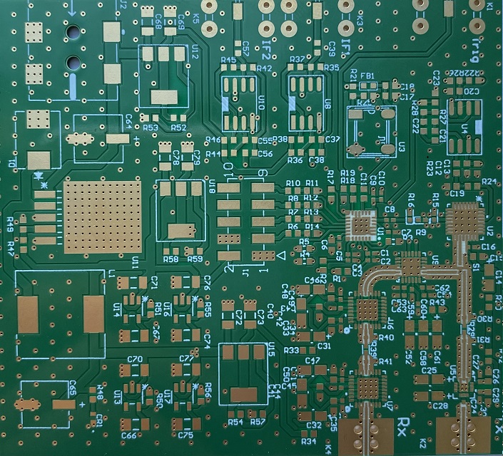
Radio-frequency and microwave designs are governed by loss and phase stability. A low-loss material keeps attenuation low enough that a feed network does not consume the link budget, and a stable dielectric constant keeps filters and couplers on frequency across the band and over temperature.
These boards are usually hybrids, with the high-frequency section on the specialised material and the digital and power sections on ordinary laminate. Keeping the expensive area as small as the design allows is the single most effective cost control, and it also simplifies impedance control by confining the sensitive transitions to one region.
Automotive and Power Electronics
Automotive electronics combines thermal cycling with vibration and long service life. Thermally conductive laminates carry heat away from power stages and LED drivers, and their dimensional stability keeps the assembly within the mechanical tolerances the enclosure demands.
In LED modules, board performance is inseparable from light output, because junction temperature sets both efficiency and lifetime. A laminate with moderate conductivity, combined with a generous copper area and a proper interface to the heat sink, often achieves the required result at lower cost than a metal-backed construction. The interfaces themselves are covered in the notes on potting and dispensing adhesives.
Selection Factors
Start with the electrical requirement: the highest frequency the board must carry, the loss the link can tolerate, and how much variation in dielectric constant the design can absorb before it stops working. That set of numbers narrows the field to one or two families before cost is considered at all.
Then apply the environment. Temperature range, humidity, chemical exposure and mechanical load each eliminate options, and they are usually specified by the end application rather than by the engineer. Finally consider cost as a whole, not per panel, because a material that removes one prototype iteration is often cheaper than the material it replaced.
Common Fabrication Challenges
Warpage is the most frequent problem. It originates in the lamination cycle and in an unbalanced copper distribution, and on thin or asymmetric stacks it appears even when the press parameters are correct. Balanced copper and a confirmed press profile are the standard countermeasures.
Drilling and copper adhesion come next. Harder materials wear tooling faster, and some chemistries bond poorly to plated copper without a treated surface or a bonding layer in the foil. Where the surface will be exposed to condensation or salt spray, a conformal coating adds protection that the laminate alone cannot provide.
Testing and Qualification
Qualification differs from ordinary production testing. Beyond electrical continuity, these materials are usually qualified by thermal cycling, moisture sensitivity level testing, and mechanical checks such as peel strength and dimensional stability after lamination. Those results are what a customer audit will ask for, and they are slow and expensive to obtain if nobody planned for them.
In-process control matters equally. Lamination pressure and temperature profiles, hole wall preparation and plating thickness all need to be recorded per lot, because a failure in any one of them may not appear until the board has been through several hundred thermal cycles in the field.
Thermal management is the reason many of these materials are chosen at all, and the laminate is only one part of it. A thermally conductive base spreads heat laterally, but the path still has to leave the board through vias, an interface material and a heat sink. Selecting a high-performance laminate without designing that complete path wastes both the material and the cost premium it carries.
FAQ
Is polyimide always the right choice for high temperature? Not always. It is the strongest option mechanically and thermally, but a high glass transition epoxy or a ceramic-filled laminate often covers the requirement at a lower cost if the peak temperature is moderate.
Can high-frequency and thermal materials be combined? Yes, and it is common. A low-loss material can be used for the radio-frequency section while a thermally conductive grade carries the power stage, bonded into one panel with a compatible prepreg.
How much does material choice affect the schedule? Significantly. Specialised laminates often carry four to six week lead times, so the material order should be placed alongside the design rather than after the layout is complete.

