Insulated Metal Substrate PCB: Structure and Applications
Heat is what limits a power electronic design, and the insulated metal substrate PCB is one of the most direct answers to it. Instead of relying on copper area and airflow to move heat away from a component, an IMS board carries that heat through a thin dielectric layer into a metal base and spreads it across the whole panel. For high-power LED modules and power converters, that single change alters what the product can do.
What an insulated metal substrate board is
An insulated metal substrate PCB is built on a metal base, usually aluminium or copper, with a thermally conductive but electrically insulating layer between the base and the circuit. Where a conventional board uses a non-metallic laminate such as FR-4, an IMS board is designed from the start for thermal management.
The benefit is direct: heat generated by the components is conducted away efficiently, which keeps junction temperatures lower, keeps the product stable in operation, and extends the life of the components on it.
The three layers
The metal base provides mechanical support and acts as the heat spreader. Aluminium is the common choice because it balances cost against thermal performance, while copper conducts heat better and is specified where the thermal load demands it.
The dielectric layer is the critical layer. It has to conduct heat while remaining an electrical insulator, which is what allows a live circuit to sit directly on a metal plate. Its thickness and thermal conductivity are the two parameters that decide how well the whole construction performs.
The circuit layer is a copper foil pattern, processed in the same way as a conventional single-sided board. Components are mounted on it as usual, and the copper carries the current in the normal way.
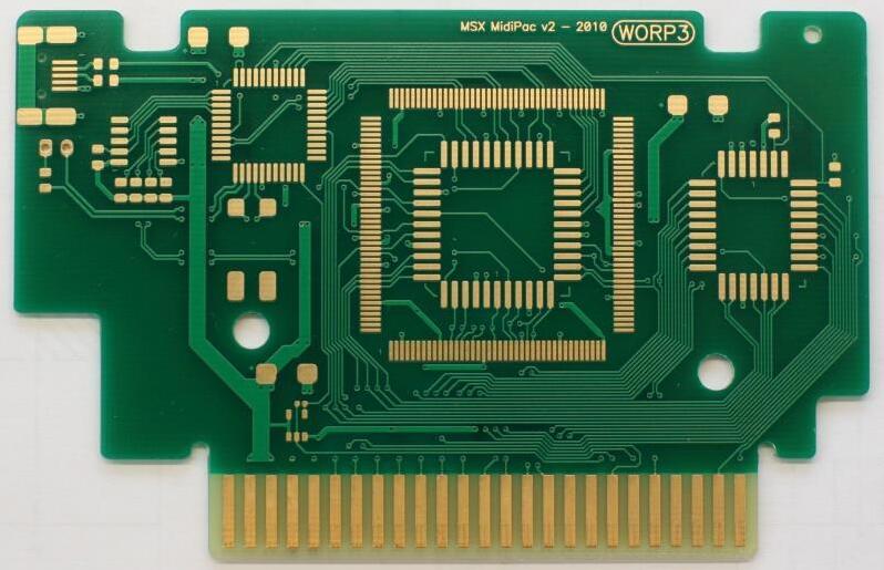
The dielectric layer is a compromise by definition: thinner and more conductive means better heat flow, but the same layer is what provides the electrical isolation.
Where the advantage comes from
Thermal performance is the headline. The metal base conducts heat far more effectively than a laminate, so the temperature rise for a given dissipation is smaller and hot spots are spread rather than concentrated. Mechanical strength is the second benefit, since a metal substrate is more robust than a thin laminate and tolerates handling and vibration better.
Electrical performance improves as a consequence of the lower thermal resistance, because components operate at a temperature closer to their specification. The practical effect is a longer service life at the same output, or a higher output from the same footprint.
Applications
LED lighting is the largest application. High-power LED modules dissipate most of their input as heat in a small area, and a metal substrate moves that heat into the fixture instead of leaving it in the junction. The same property makes IMS boards suitable for modules that must run at high drive current without colour shift or premature failure.
Automotive electronics uses them for power regulators, motor controllers, and LED headlamps, where the ambient temperature is high and the board is expected to last the life of the vehicle. Power conversion and industrial control follow, because power modules and automation equipment benefit from a stable thermal path, and renewable energy systems such as solar inverters and wind conversion equipment depend on thermal reliability over decades.
Materials
The base is usually aluminium, chosen for the balance of cost and thermal performance, with copper specified where conduction has to be better still. The dielectric layer must combine high thermal conductivity with electrical insulation, and its specification is where the design trade-off is made. Surface finishes such as electroless nickel immersion gold and hot air solder levelling improve solderability and resist oxidation, with the choice depending on the assembly process and the required shelf life.
Design points
Thermal strategy comes first: where the heat is generated, where it is allowed to go, and how much copper area is available to help it spread. Stackup and material selection follow, since the thickness and the thermal conductivity of the dielectric layer set the thermal resistance between the circuit and the base.
Manufacturability closes the loop. Because IMS constructions are usually single-sided, the routing has to be planned with that limitation in view, and the features that cannot be produced on the intended process should be identified before the design is released. Copper area also serves the thermal path directly, and the rules for using it well are discussed in our guide to copper flooding, mesh or solid.
<img src="https://www.gopcba.com/wp-content/uploads/2026/09/1,.jpg" alt="Aluminium base board for high power LED modules” />
A metal substrate spreads heat only as well as the dielectric lets it through. The layer that carries the heat is the same layer that provides the isolation, which is why its thickness is the central decision.
Manufacturing flow
Fabrication begins with base preparation, where the metal plate is cut to size and cleaned so that the dielectric can bond reliably. The circuit layer is then formed by etching or by an additive process, followed by drilling and plating for the through connections the design requires.
The board is completed with solder mask and a final surface finish that supports component attachment and protects the copper from oxidation. Because the base is metal, handling and tooling differ from a laminate process, and the parameters used for a conventional board do not transfer unchanged.
Challenges
Thermal expansion is the first challenge. The metal base, the dielectric, and the copper circuit expand at different rates, so the material combination has to be matched to keep that mismatch from creating stress; the general mechanism is described under PCB dimensional stability and expansion.
Cost is the second. An IMS board costs more than a laminate board of the same size, and the justification is total cost of ownership: a product that runs cooler lasts longer and needs less field support. The third is the design limitation of a single conductive layer, which constrains routing and makes layout planning more important than it would be on a multilayer board. Where a protective coating is also required, the materials used on power assemblies are covered in our guide to conformal coating for board protection.
Where the substrate stops being the answer
An IMS board is not a substitute for a thermal design; it is one element of it. If the component cannot transfer its heat into the copper, or if the fixture cannot accept the heat the base collects, a metal substrate only moves the bottleneck. The thermal path should be traced from junction to ambient before the material is chosen, because that is the exercise which shows whether the substrate is the limiting element or something else is.
FAQ
When should I choose an IMS board instead of FR-4? When the heat cannot leave the component fast enough through copper and airflow alone. If the junction temperature of a power device is the limiting factor, the substrate becomes part of the thermal solution.
Is aluminium always the right base? It is the common choice. Copper is used where the thermal load is more demanding, and the decision is usually made by comparing the required thermal resistance against the cost target.
Can an IMS board be multilayer? Metal-core constructions with more than one conductive layer exist, but they are more complex and more expensive. Most designs keep the construction to a single circuit layer and solve the rest of the routing elsewhere.