Industrial Robot PCB: Design for Motion Control
An industrial robot controller is a board that has to survive its own electrical environment. Motor drives switch hundreds of volts in microseconds, the sensors are wired over cables that run the length of a factory floor, and the installation is fed from a supply shared with welding equipment. An industrial robot PCB is designed for immunity first and functionality second.
What the Controller Board Carries
The motion control section generates the pulse trains or the field oriented commands that drive each axis, and it usually runs closed loop from encoder feedback. Around it sit the fieldbus interfaces that connect the robot to its cell controller, the digital and analog inputs, and the safety circuit that can remove drive power independently of the processor.
Power conversion may or may not be on the same board. Where it is, the board carries a rectifier or a DC link, the inverter stage and its gate drive, which means the noise source and the sensitive measurement circuitry share one substrate. That combination defines the layout.
Separating Power and Control
The first principle is that the high current switching path and the signal path must not share a return. The inverter ground carries large currents with fast edges, and any impedance shared with the encoder or analog measurement ground converts a fraction of that current into an error in the measured signal.
In practice this means separate ground regions joined at one point, ideally at the DC link capacitor, and careful routing so that the gate drive return stays inside the power region. The arrangement resembles the split that a mixed signal design uses, and the reasoning is set out in ground routing and power trace planning.
Isolation and Encoder Interfaces
Encoders are wired over cables that run beside motor power conductors, so their signals arrive at the board carrying common mode noise. Every encoder input is therefore isolated or at least differentially received with a high common mode range, and the isolation barrier is a defined region of the board with its own creepage and clearance.
The barrier has to survive a test at the working voltage, and the components crossing it must be rated for the transient the installation can produce. The reference ground on the field side must not be connected to the logic ground anywhere except through the isolated converter or optocoupler, or the isolation is defeated and the noise comes straight into the processor.
EMC Immunity in the Factory Environment
An industrial installation is electrically hostile. Contactors open and close, variable frequency drives inject harmonics into the supply, and welding currents flow through the building earth. The board has to keep working through all of it, which means protection on every field connection rather than only on the ones that seem exposed.
Transient suppressors, series impedances and common mode chokes on the field wiring entry points are the standard measures, applied as close to the connector as the layout allows. They should be placed at the connector edge so that the transient is diverted before it travels across the board, and the return path for the diverted current must not pass under the processor. The general suppression principles are covered in mixed signal PCB design guidelines.
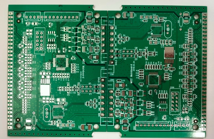
<img src="https://www.gopcba.com/wp-content/uploads/2026/08/pcb3.jpg" alt="Motor drive and control sections on a robot controller board” />
Thermal Design for Continuous Duty
A robot controller runs continuously, often at an elevated ambient inside a cabinet, and it is expected to do so for years without intervention. That makes thermal design a long term reliability matter rather than a peak performance matter. Junction temperatures running close to their limit shorten the life of every electrolytic capacitor and semiconductor on the board.
The thermal path starts with copper area under each dissipating device and continues through thermal vias into the internal planes, and it ends with the cabinet rather than with the board. Where the board is mounted on a metal panel, a defined thermal interface at the mounting points makes the panel part of the heat sink, and the mounting design is described in board outline and mounting design.
Stackup and Layer Planning
A robot controller stackup is arranged around the barriers rather than around the signal count. The drive voltage and the field voltages each need their own separation, and the isolation barriers are physical regions that no plane may cross. That usually means several ground planes that are not connected to each other, which is a different arrangement from an ordinary digital board.
The signal layers are then assigned so that every high speed interface has a continuous reference beneath it and no interface crosses a plane boundary. Where two adjacent layers carry the same interface, orthogonally routing them reduces crosstalk without any additional spacing, which is valuable on a board where the components are already crowded.
Connectors, Wiring and Serviceability
Field connections are made through pluggable terminal blocks or heavy duty connectors, and the entire mechanical load of a cable harness is transmitted into the board through those joints, which is why they are the most common site of mechanical failure on this class of equipment. Connector pads need generous copper and often additional mechanical fixing, because a connector that is held only by solder will eventually crack under vibration and cable pull.
Serviceability matters as much as reliability. An indicator per axis, accessible test points on the supply rails and a clear silkscreen legend reduce the time an engineer spends diagnosing a machine that has stopped production. Connector numbering should match the drawing that the maintenance team uses, not the internal net names.
Safety Circuits
The safety function that removes drive power must not depend on the processor being healthy or on its firmware behaving correctly. It is implemented with a separate path, usually a dual channel arrangement with monitoring, that de-energises the drive independently and reports the state back. On the board, that means dedicated components and dedicated routing that cannot be disabled by a firmware fault.
That circuitry is also the place where the creepage and clearance requirements are most severe, because it handles the drive voltage and it must operate correctly after a fault has already occurred elsewhere on the board. The layout must assume that the fault condition persists while the safety path acts, so no single component failure may leave the drive energised. Keeping it physically separate from the rest of the board and clearly marked on the silkscreen helps both the certification engineer and the technician.
FAQ
Should the drive stage be on the same board as the controller? It can be, provided the ground and the isolation are handled deliberately. A separate drive board simplifies the noise problem at the cost of an interconnect, and the choice usually follows from the mechanical layout of the cabinet.
How many layers does a robot controller need? Six to ten layers is typical, driven by the number of separate supplies, the isolation barriers and the need for a continuous reference plane beneath the high speed interfaces.
Is conformal coating necessary? In a factory environment it is usually worthwhile, because conductive dust and humidity are both present. The coating must be compatible with the connectors and with any test points that have to stay accessible, as described in conformal coating and board protection.