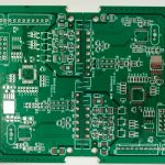
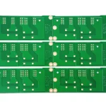
LEDs are widely used in streetlights, automotive headlights, smartphone flashes, industrial lighting, displays, medical devices, and smart lighting systems. At the center of these lighting products is the LED PCB, a specialized circuit board designed to distribute electrical power, manage heat, support LED components, and maintain reliable operation.
Compared with conventional printed circuit boards, an LED PCB often needs to handle both electrical and thermal requirements. In high-power lighting applications, the choice of substrate, copper thickness, thermal path, LED placement, driver circuit, and soldering process can directly influence the performance and service life of the final product.
This article provides a practical overview of LED PCB Assembly, including what an LED circuit board does, common LED PCB types, key components, the assembly process, major manufacturing challenges, inspection and testing methods, and how Kingda supports custom LED PCB and PCBA projects.
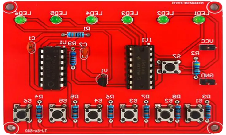
What Is LED PCB Assembly?
LED PCB Assembly is the process of mounting and soldering LED components and related electronic components onto a printed circuit board.
A typical LED PCBA may contain:
- SMD LEDs
- LED driver ICs
- Resistors
- Capacitors
- Connectors
- Sensors
- Protection components
- Control circuits
The PCB must provide stable current distribution while also transferring heat away from the LED package.
For high-power LEDs, effective thermal management is particularly important. Excessive operating temperature can reduce efficiency, accelerate component degradation, affect color stability, and shorten product life.
The typical manufacturing workflow is:
PCB Fabrication → Solder Paste Printing → Component Placement → Reflow Soldering → Inspection → Electrical Testing → Functional Testing
What Does an LED Circuit Board Do?
An LED circuit board performs several functions within a lighting system.
Power Distribution
Copper traces distribute electrical current from the power source to LED components and driver circuits.
For high-power products, designers need to consider:
- Trace width
- Copper thickness
- Current capacity
- Voltage drop
- Grounding
- Power distribution
Heat Management
LEDs generate heat during operation. The PCB provides a thermal pathway that helps transfer heat away from the LED package.
Depending on the product, this may involve:
- Aluminum PCB
- Metal-core PCB
- Thermal vias
- Copper heat-spreading areas
- Heat sinks
- Thermal interface materials
Component Support
The PCB provides a stable mounting platform for LEDs, driver ICs, passive components, sensors, and connectors.
Lighting Control
Advanced LED control boards can incorporate circuits for:
- Dimming
- Color adjustment
- Color-temperature control
- Motion sensing
- Wireless communication
- Automatic brightness adjustment
This allows LED PCBs to function as part of smart lighting and IoT systems rather than simply supplying power to LEDs.
Types of LED PCB Boards
Different applications require different PCB structures. Common options include aluminum LED PCBs, FR-4 LED PCBs, flexible LED PCBs, and multilayer LED PCBs.
Aluminum LED PCB
The Aluminum LED PCB is one of the most common PCB solutions for high-power LED applications.
A typical metal-core construction consists of a copper circuit layer, an electrically insulating dielectric layer, and a metal base.
Advantages
- Good thermal management
- Strong mechanical stability
- Suitable for high-power LEDs
- Good cost-to-performance balance
- Suitable for volume manufacturing
Typical Applications
- Automotive headlights
- Streetlights
- Industrial lighting
- Outdoor lighting
- LED floodlights
- LED signage
FR-4 LED PCB
FR-4 LED PCBs are suitable for lower-power LED products where extreme thermal performance is not required.
Applications include:
- Indicator lights
- Consumer electronics
- Toys
- Small appliances
- Low-power LED circuits
- Decorative electronics
FR-4 is generally more economical and widely available, but it does not provide the same thermal path as metal-core PCB constructions.
Flexible LED PCB
A Flexible LED PCB typically uses polyimide or another flexible substrate.
It can bend around curved surfaces and fit into restricted spaces.
Common applications include:
- LED strips
- Automotive interior lighting
- Wearable electronics
- Curved displays
- Compact medical devices
- Decorative lighting
Multilayer LED PCB
A Multilayer LED PCB is useful when an LED system includes additional control, sensing, communication, or power-management circuits.
Applications may include:
- Smart lighting
- Automotive lighting modules
- Stage lighting
- IoT lighting systems
- Intelligent lighting controllers
The multilayer structure provides more routing space but increases manufacturing complexity and may require additional thermal analysis.
Key Components of an LED Circuit Board
A complete LED PCB Assembly may integrate several key components.
LED Components
The LED package determines important characteristics such as:
- Brightness
- Color
- Efficiency
- Thermal behavior
- Optical performance
The LED package must be matched to the PCB and soldering process.
PCB Substrate
Common substrate materials include:
- FR-4
- Aluminum
- Copper
- Ceramic
- Polyimide
Selection depends on power, temperature, flexibility, electrical insulation, mechanical requirements, and cost.
Copper Traces
Copper traces carry current to the LEDs and other circuits.
For higher-current designs, trace width and copper thickness should be determined according to the required current and allowable temperature rise.
Resistors
Resistors may be used for current limiting, sensing, biasing, or other control functions depending on the circuit architecture.
LED Driver IC
Higher-performance lighting systems frequently use a dedicated constant-current LED driver.
An LED driver can provide:
- Stable current regulation
- Dimming
- Protection
- Improved energy efficiency
- Color or brightness control
Thermal Vias and Heat Dissipation Structures
High-power LED designs may use thermal vias, large copper areas, aluminum substrates, heat sinks, or other thermal-management structures to transfer heat away from the LED package.
LED PCB Assembly Process
A professional LED PCB Assembly process should combine accurate component placement, controlled soldering, inspection, and functional validation.
1. PCB Design and Prototyping
Before manufacturing begins, engineers should evaluate:
- LED arrangement
- PCB dimensions
- Thermal path
- Current capacity
- Driver circuit
- Component clearances
- Assembly requirements
- Environmental conditions
Prototype production can validate electrical performance, thermal behavior, LED positioning, and mechanical integration before volume manufacturing.
Kingda provides DFM/DFA engineering support, PCB fabrication, rapid prototyping, and PCB assembly services, supporting projects from design through production. (Kingda)
2. Component Sourcing
A typical LED PCBA BOM may include:
- LEDs
- Driver ICs
- Resistors
- Capacitors
- Connectors
- Sensors
- Protection components
Component availability can directly influence production schedules, particularly for turnkey projects.
Kingda provides components procurement and BOM support as part of its one-stop PCBA manufacturing service. (Kingda)
3. Solder Paste Printing
Solder paste is applied to PCB pads using a stencil.
The printing process must control:
- Paste volume
- Stencil alignment
- Aperture dimensions
- Printing pressure
- Board flatness
Consistent solder-paste deposition is essential for reliable solder-joint formation.
4. Pick-and-Place Assembly
Automated pick-and-place machines position LEDs and other SMD components according to the approved PCB data.
For LED arrays, placement accuracy is especially important because component-position variation can affect optical alignment and light distribution.
5. Reflow Soldering
The populated board passes through a controlled reflow oven.
The reflow profile should consider:
- LED package specifications
- Solder-paste chemistry
- PCB material
- Component temperature ratings
- PCB thermal mass
A properly controlled reflow process minimizes solder defects while protecting temperature-sensitive components.
6. Inspection and Testing
After soldering, the assembly is inspected and tested.
Typical methods include:
- SPI
- AOI
- X-ray inspection
- Electrical testing
- Functional testing
Kingda’s published quality-control flow is:
IQC → SPI → SMT/THT Assembly → AOI → X-Ray → ICT/FCT → OQC
Its inspection capabilities include 3D SPI, AOI, X-ray, FAI, ICT, FCT, and customized testing. (Kingda)
Major Challenges in LED PCB Assembly
1. Thermal Management
Heat is one of the biggest challenges in high-power LED PCB Assembly.
Poor thermal performance can lead to:
- Reduced LED efficiency
- Thermal degradation
- Color instability
- Solder-joint stress
- Reduced product lifetime
Solutions
Use suitable:
- Aluminum LED PCBs
- Metal-core PCB structures
- Thermal vias
- Copper heat-spreading areas
- Heat sinks
- Thermal interface materials
2. Component Placement Precision
LED arrays require accurate component positioning.
Placement errors may affect:
- Optical alignment
- Light distribution
- Product appearance
- Electrical connections
Automated placement and AOI can significantly reduce these risks.
3. Material Selection
The right PCB substrate depends on the application’s electrical, mechanical, and thermal requirements.
| LED PCB Type | Main Advantage | Typical Application |
|---|---|---|
| FR-4 LED PCB | Low cost | Low-power electronics |
| Aluminum LED PCB | Thermal management | Automotive and high-power lighting |
| Flexible LED PCB | Bendability | LED strips and curved lighting |
| Ceramic LED PCB | High thermal performance | Specialized high-power applications |
| Multilayer LED PCB | High circuit density | Smart lighting systems |
4. Solder Joint Reliability
Poor soldering can cause:
- Open circuits
- Intermittent connections
- Short circuits
- Mechanical failures
- Thermal problems
Common LED PCBA defects include:
- Cold solder joints
- Solder bridging
- Poor wetting
- Tombstoning
- Excessive solder voiding
Proper stencil design, placement accuracy, and reflow-process control are essential for reducing these defects.
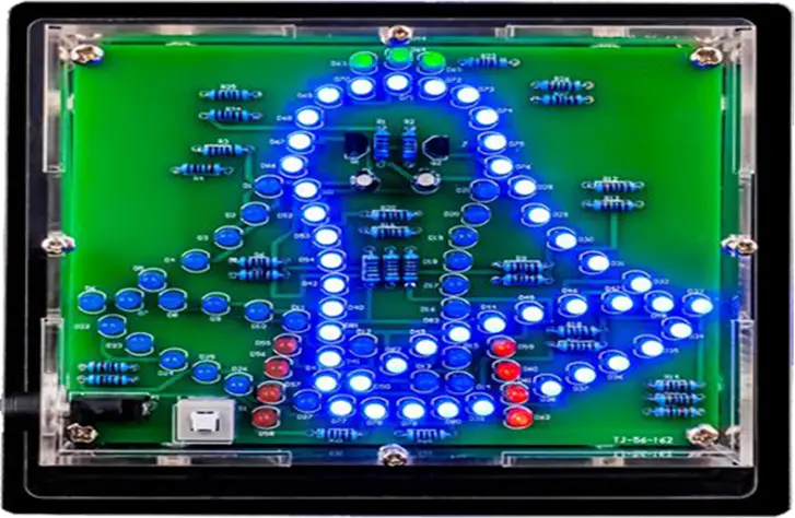
LED PCB Inspection and Testing
Visual Inspection
Visual inspection can identify:
- Component orientation problems
- Soldering defects
- PCB damage
- Incorrect components
- Mechanical defects
SPI
Solder Paste Inspection (SPI) verifies the solder-paste volume and position before component placement.
AOI
Automated Optical Inspection (AOI) can detect:
- Missing components
- Incorrect placement
- Polarity errors
- Solder bridges
- Visible solder defects
X-Ray Inspection
X-ray inspection is useful for hidden solder joints and advanced component packages.
Electrical Testing
Typical testing can include:
- Continuity
- Insulation
- ICT
- Functional testing
LED Functional Testing
A completed LED PCBA may require application-specific functional tests such as:
- LED illumination
- Current
- Voltage
- Driver operation
- Dimming
- Color control
- Communication functions
Thermal Testing for LED PCBs
For high-power products, thermal testing should be included during engineering validation.
Testing may evaluate:
- Temperature rise
- PCB hot spots
- Heat-sink performance
- Thermal interface performance
- Operating stability
- Long-term thermal behavior
Thermal imaging can help engineers identify localized heat concentration and optimize the PCB layout or cooling structure.
LED PCB Manufacturing Considerations
A reliable LED PCB manufacturer should control the complete process from material selection through assembly.
Material Selection
The PCB material should be matched to:
- LED power
- Operating temperature
- Heat dissipation requirements
- Mechanical structure
- Electrical insulation
- Environmental conditions
Copper Thickness
High-power LED circuits may require wider traces or thicker copper to handle current and control temperature rise.
Surface Finish
Common finishes include:
- HASL
- Lead-free HASL
- ENIG
- OSP
- Immersion Tin
- Immersion Silver
The final selection should consider assembly requirements, reliability, cost, and component compatibility.
Thermal Structure
The PCB must provide an efficient thermal path from the LED package toward the heat-dissipation structure.
Kingda LED PCB Manufacturing and Assembly Advantages
For customers looking for an experienced LED PCB manufacturer and LED PCB Assembly supplier, Kingda provides an integrated PCB and PCBA manufacturing solution.
Kingda was founded in 2013 and provides a one-stop manufacturing workflow covering PCB design and development, PCB manufacturing, component procurement, SMT, DIP, finished-product assembly, and testing. The company states that it serves customers in industries including automotive, medical, industrial automation, AI, smart home, security, power, and communications. (Kingda)
One-Stop LED PCB and PCBA Services
Kingda can integrate:
PCB Design Support → PCB Fabrication → Component Sourcing → SMT/THT Assembly → Inspection → Testing → Final Assembly
This allows customers to manage PCB fabrication, component procurement, assembly, and testing through one manufacturing partner. (Kingda)
Engineering and DFM/DFA Support
LED products require coordination between electrical design, thermal performance, component placement, and manufacturability.
Kingda provides professional engineering support for PCB design review, DFM analysis, and manufacturing optimization. Its PCB manufacturing service states that its engineering team can provide technical guidance and review customer designs to reduce design-related production risks. (Kingda)
SMT, THT, and Mixed-Technology Assembly
Kingda supports SMT, THT, and mixed-technology PCB assembly, allowing LED assemblies with both surface-mount and through-hole components to be manufactured through the same production system. Kingda specifically lists LED Lighting among the applications for its mixed-technology assembly service. (Kingda)
Comprehensive Quality Control
Kingda’s published quality process is:
IQC → SPI → SMT/THT Assembly → AOI → X-Ray → ICT/FCT → OQC
It provides:
- 3D SPI
- AOI
- X-ray inspection
- First Article Inspection
- ICT
- FCT
- Customized testing solutions
This provides multiple inspection stages for LED PCB assemblies from incoming materials through final shipment. (Kingda)
Quality Certifications
Kingda reports certifications including:
- IATF 16949:2016
- ISO 13485:2016
- ISO 9001:2015
- ISO 14001:2015
- UL
- IPC membership
These certifications and qualifications support manufacturing requirements across automotive, medical, industrial, and other demanding applications. (Kingda)
Traceability and Production Management
Kingda states that its ERP-based system supports production traceability throughout the manufacturing process. Its published information also highlights multiple production lines, real-time production monitoring, and delivery management. (Kingda)
Prototype to Mass Production
Kingda supports rapid PCB prototyping, low-volume production, and high-volume PCB assembly, allowing LED product developers to move from prototype validation to larger-scale manufacturing within the same supply chain. (Kingda)
LED PCB Applications
LED PCB Assembly is widely used in:
- Automotive lighting
- Streetlights
- Industrial lighting
- LED displays
- Consumer electronics
- Medical equipment
- Smart lighting
- Outdoor signage
- Wearable electronics
- IoT lighting systems
For automotive and industrial applications, thermal performance and reliability are particularly important. For consumer and decorative products, flexible construction, compact size, and appearance may receive greater priority.
How to Choose the Right LED PCB Manufacturer
Before selecting an LED PCB Assembly manufacturer, evaluate the following:
Thermal Capability
Can the supplier manufacture aluminum, metal-core, ceramic, and flexible LED PCBs?
Assembly Capability
Does the supplier support:
- SMT
- THT
- Mixed Technology
- Fine-pitch components
- Reflow soldering
- Selective soldering
Engineering Support
Can the manufacturer provide:
- DFM
- DFA
- PCB design review
- Thermal design feedback
- BOM analysis
- Component alternatives
Inspection and Testing
Does the supplier offer:
- SPI
- AOI
- X-ray
- ICT
- FCT
- Functional LED testing
Supply Chain Support
Can the manufacturer source LED packages, driver ICs, passive components, connectors, and other components?
Production Scalability
Can it support:
Prototype → Low Volume → Pilot Production → Mass Production
Conclusion
LED PCB Assembly is a critical part of modern LED lighting and electronic products. The PCB must not only provide reliable electrical connections but also distribute current, manage heat, support components, and maintain long-term stability.
Choosing the correct LED PCB type is the first step. Aluminum LED PCBs are widely used for high-power lighting, FR-4 LED PCBs are suitable for many low-power applications, Flexible LED PCBs support curved and space-constrained designs, while multilayer and ceramic LED PCBs provide solutions for more sophisticated requirements.
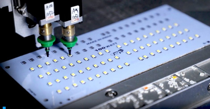
The assembly process is equally important. Solder paste printing, precision pick-and-place, reflow soldering, SPI, AOI, X-ray inspection, electrical testing, and functional testing all contribute to the reliability of the final LED PCBA.
For companies looking for a reliable LED PCB manufacturer and LED PCB Assembly partner, Kingda combines PCB fabrication, component sourcing, SMT/THT assembly, DFM/DFA engineering, inspection, testing, rapid prototyping, low-volume manufacturing, and high-volume production. (Kingda)