A Dk 3.38 Low-Loss Laminate for 5G and 77 GHz Radar
One material profile keeps appearing in radio-frequency designs: a ceramic-filled hydrocarbon laminate with a dielectric constant of about 3.38 and a dissipation factor around 0.0027. Those two numbers place it in a specific niche, well above the performance of ordinary FR-4 and well below the cost of the most exotic low-loss materials, which is why it turns up in so many 5G and radar boards.
The Material Profile
A dielectric constant of 3.38 is stable across a wide frequency range, which is the property that matters more than the absolute value. A material whose Dk drifts with frequency forces the designer to accept impedance excursions across the band, while a stable one keeps a single trace geometry valid from a few hundred megahertz to tens of gigahertz.
The dissipation factor of 0.0027 is roughly an order of magnitude better than standard FR-4 and is the reason the material remains usable at millimetre-wave frequencies. It sits between the best unfilled PTFE grades and the general-purpose high-frequency laminates.
Electrical Performance
Because the Dk is moderate rather than very low, trace widths for a 50 ohm line stay practical at commonly available dielectric thicknesses. That matters for manufacturing yield, since a very narrow trace on a very thin dielectric leaves little room for etch tolerance before the impedance leaves its window.
Stable electrical behaviour also simplifies impedance control across a mixed design. Filters, couplers and feed networks all depend on the same dielectric constant, so a single material specification keeps every element of an antenna feed consistent rather than requiring each one to be tuned separately.
Thermal and Mechanical Behaviour
Thermal conductivity around 0.71 W/mK is modest but useful, and combined with a low coefficient of thermal expansion it keeps dimensional change small across the operating temperature range. For a phased array, that stability is worth more than raw conductivity, because dimensional drift steers the beam.
Mechanically the material is rigid enough to be handled in multilayer constructions, which distinguishes it from unfilled PTFE grades that are soft and prone to cold flow. Higher rigidity makes drilled holes more reliable and keeps the panel flat through the lamination cycle, both of which directly affect via quality.
Where It Is Used: 5G Infrastructure
Massive MIMO antenna arrays in 5G infrastructure need hundreds of feed lines whose phase relationship must hold across the array. Any variation in dielectric constant between boards becomes a beam pointing error that no calibration can fully remove, so stability is the governing requirement.
The same properties suit millimetre-wave bands at 28 and 39 GHz, where the loss budget is tight and the antenna elements are small. Base station radio units, small cells and test equipment for those bands are all natural applications.
Where It Is Used: 77 GHz Radar
Automotive radar at 24 and 77 GHz is the fastest growing use. A radar module needs a material whose properties hold from the cold end of the automotive range to the hot end, because a shift in dielectric constant moves the antenna resonant frequency and reduces the effective aperture.
The low dissipation factor also matters directly at 77 GHz, where loss in the feed network reduces the signal that reaches the antenna. And because the module is soldered rather than connectorised in many designs, the material must survive the reflow profile without dimensional change that would de-tune the array.

Aerospace, Satellite and Wireless Devices
Aerospace and satellite payloads use the same class of material where thermal cycling, humidity and vibration are all specified rather than assumed. The qualification evidence for the material, and its traceability from panel to board, become part of the procurement requirement rather than optional documentation.
Wireless devices occupy the other end of the range, using the material only for the radio-frequency section of a board that is otherwise built on ordinary laminate. In that role it delivers the electrical performance required at a cost that a consumer product can absorb.
Hybrid Stackups and Material Comparison
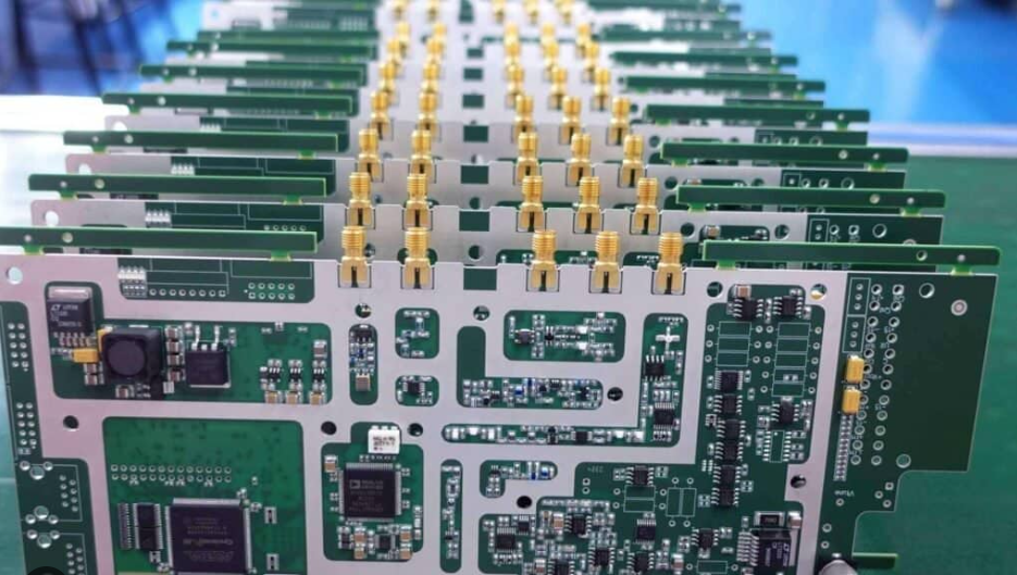
Most production boards are hybrids. The radio-frequency section uses the high-frequency laminate, while the digital and power sections stay on FR-4, bonded into one panel with a compatible prepreg. Cost then scales with the area that genuinely needs the performance rather than with the whole board.
Compared with FR-4, the gain is a stable dielectric constant and far lower loss, at several times the material cost. Compared with an unfilled PTFE laminate, the gain is easier processing and better mechanical behaviour, at some cost in loss. Compared with grades optimised for higher thermal conductivity, the trade runs the other way, which is why the choice depends on whether the limiting factor is loss or heat.
Sourcing and Cost
Material cost for this class of laminate runs several times an equivalent FR-4 panel, and the fabrication premium adds to that. The levers that reduce total cost are the same ones that reduce risk: keep the high-frequency area as small as the design allows, hold the stackup to the thicknesses the fabricator stocks, and avoid unnecessary process steps such as sequential lamination.
Availability deserves attention. Typical lead times run four to six weeks depending on grade and demand, so planning the material order alongside the design schedule prevents a situation where the board is ready and the laminate is not. Qualifying a second source early is worth the paperwork.
Where a Low-Loss Laminate Is Genuinely Required
The decision should follow the loss budget rather than the frequency alone. Below roughly 2 GHz conductor loss in the copper dominates, and a smooth foil on an ordinary laminate can be sufficient. Above about 10 GHz the dielectric term takes over, and at that point a low-loss laminate is the only lever that still changes the outcome.
Phase stability is the second trigger. A narrow-band filter or a phased array is sensitive to the dielectric constant even when its loss would be perfectly acceptable, because a small shift moves the centre frequency or steers the beam. Those designs justify the material for a reason that has nothing to do with attenuation.
A third case is thermal. A power amplifier driving an antenna needs both low loss and a path for heat, and a low-loss laminate with moderate thermal conductivity combined with a thermal via array often solves both problems without moving to a metal-backed construction.
Working With the Material in Production
Processing this class of material is closer to ordinary FR-4 than to unfilled PTFE, which is a large part of its appeal. It drills and routes with standard tooling, laminates with conventional press cycles, and accepts the same surface finishes as any other high-frequency board.
The process points that still need attention are hole wall preparation and lamination parameters. Both should be specified by the laminate supplier and confirmed by the fabricator rather than inferred from experience with a different material, because the failure modes are delamination and unreliable plating, and both are expensive to discover after the panel has been built.
Finally, describe the material in the fabrication package by its properties rather than by a part number alone. Stating the required dielectric constant, dissipation factor and thickness range lets a fabricator propose an equivalent and lets a second source be qualified without repeating the entire design cycle.
FAQ
Is a Dk of 3.38 suitable for millimetre-wave design? Yes, into the 77 GHz range, provided the trace geometry and transitions are designed for that band. The dissipation factor is low enough that dielectric loss is no longer the dominant limitation for typical trace lengths.
Can this material be mixed with FR-4 in one stackup? Yes, and it usually is. The transition between materials needs care, because the dielectric constant changes and the impedance shifts locally at the boundary.
What is the main manufacturing risk? Delamination and hole wall quality. Both depend on the lamination cycle and the hole preparation process for this specific material, so qualifying the fabricator on the material matters more than comparing datasheet values.