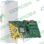
Medical PCB Prototyping to Production: Process and Requirements
A medical PCB is not simply a well made circuit board. It is a board whose behaviour has to be demonstrable, whose materials have to be traceable, and whose process has to stay identical from the first prototype to the ten thousandth unit. That combination is what separates medical electronics from consumer work, and it shapes the prototype stage before any volume commitment is made.
What a Medical PCB Prototype Has to Prove
The prototype exists to answer three questions at once. Does the circuit work electrically, does it pass the regulatory tests it will be measured against, and can it be built in volume without drifting away from the validated configuration. A prototype built with hand selected parts and a different stackup answers only the first question, and the cost of that shortcut appears later.
Prototype quantity follows from those questions rather than from habit. Five to fifty pieces cover functional verification and design review, while fifty to two hundred are typically needed for certification testing, software validation and clinical evaluation, because those activities consume hardware in ways that bench testing does not.
Electrical Requirements in the Prototype
Signal integrity work should be finished at prototype stage. Low level analogue channels, which carry electrocardiogram or sensor signals in the microvolt range, sit on the same board as switching supplies and digital buses, and the separation has to be designed rather than tuned. The layout rules for that mixture are set out in mixed signal PCB design guidelines.
Where the board carries radio or high speed interfaces, impedance control has to be specified as a tolerance with a test coupon, not as a nominal figure. A medical PCB that leaves impedance control to the fabricator without a coupon has no evidence that the requirement was met, and evidence is the currency of a regulated product.
Material Selection and Traceability
Materials are chosen for thermal and mechanical margin rather than for cost. A high glass transition laminate resists the thermal load of repeated reflow, and a polyimide layer is used where the assembly is flexible or where repeated sterilisation is expected. The laminate must also be compatible with the cleaning and sterilisation method, since some chemicals attack the resin and some temperatures exceed its rating.
Traceability runs from the laminate batch and the copper foil through lamination, drilling, plating and assembly, with records kept for the life of the product. RoHS and REACH declarations are collected for every material, and a change of supplier for a laminate or a solder mask is a change to the device, which means the documentation has to be updated and the change assessed.


The Prototype to Production Transition
The step from prototype to volume carries the highest risk in the whole programme. Yield moves when panelisation and tooling change, component life cycles become visible once the bill of materials is fixed, and unit cost only falls if the design was made for the process that will actually run it. Each of those is an engineering task rather than a purchasing task, and each one is easier to solve while the volume process is still being chosen.
Panel design is the most common source of trouble, because a panel that suits a small run may not suit the assembly line that will build the volume, and a change of panel changes the stencil and the placement programme. Where the design is revised, an engineering change process with a defined approval route keeps the validated build and the production build in step, and it also preserves the link between a delivered unit and the configuration it was built to.
Quality Systems and Regulatory Documents
ISO 13485 is the quality standard that governs medical device manufacture, and it requires documented procedures, trained operators, controlled suppliers and corrective action records. A fabricator holding that certification is not automatically suitable, but one without it cannot support a device that will be audited.
Process capability matters as much as the certificate. IPC Class 3 is the usual acceptance level for medical hardware, and it tightens annular ring, plating thickness and inspection requirements compared with the Class 2 level common in consumer products. The board that will eventually be audited should be built to that level from the first prototype, so that no requalification is needed later.
Testing and Inspection Regime
Electrical test is one hundred per cent, not sampled. Flying probe or fixture test verifies continuity and isolation on every board, and automated optical inspection checks the assembly for placement and solder defects. X-ray inspection is added where area array packages or hidden joints make optical inspection meaningless.
Reliability testing is where the design is challenged rather than the process. Thermal cycling reveals solder joint fatigue, humidity and bias testing reveals insulation weakness, and stress screening removes the early life failures that would otherwise appear in the field. Each test should have a defined acceptance criterion and a defined action if it fails.
Cost and Lead Time Structure
Prototype pricing reflects set up as much as material. A four layer medical board may cost eighty to two hundred dollars for a small run, a six to eight layer board more, and assembly adds its own tooling and programming charges. Volume pricing is a different calculation, driven by layers, finish, test level and order quantity.
Lead time for prototypes is commonly five to ten working days, and volume production settles into a repeatable schedule once tooling is fixed. Compression of either figure below the process capability is the usual cause of a quality excursion, so the schedule should be set from the process rather than negotiated against it.
Working With the Fabricator
A medical programme is easier when the fabricator is involved before the layout is frozen. Design rule review at that stage catches annular ring and spacing problems while they are still free to fix, and the panel design can be agreed with the assembly line rather than imposed on it. Waiting until the Gerber files are released turns each of those into a change order.
Documentation travels with the board. A controlled drawing states the stackup, the material, the finish, the acceptance class and the test requirements, and a first article inspection report confirms that the delivered panel matches it. That record is the evidence a notified body will look for, and it is far easier to produce if it was generated during the build rather than reconstructed afterwards. Controlled impedance structures, for example, need the coupon described in HDI board CAM methods to be meaningful.
FAQ
Does a medical PCB need a special laminate? Not always, but the laminate must be justified. High glass transition material is common, polyimide appears where flexibility or repeated sterilisation is required, and ceramic substrates appear in high power or implantable designs.
Can a consumer board be upgraded to medical grade? The board can be rebuilt to Class 3, but the change of materials, process and documentation constitutes a new device, and the qualification evidence has to be produced again.
How much documentation is required? Enough that any unit can be traced to its material batches and process records, and that any change can be shown to have been assessed and approved. A conformal coating, referenced in conformal coating and board protection, is a good example of a process step that needs a written specification.