Heat Sink Bonding: 6 Rules for a Reliable Thermal Joint
Heat sink bonding attaches a metal sink, a stiffener or a shield to a board with a filled adhesive that has to conduct heat, hold mechanically and survive the thermal cycles of service. It replaces screws and clips where the back of the board must stay flat or where the joint has to spread heat over an area. It is used on power supplies, motor drives and LED boards, wherever a hot component sits on a small footprint.
The joint is only as good as its bond line, and the bond line is decided by four things: the surface, the adhesive, the thickness and the cure. Get any of them wrong and the assembly can look perfect while running far hotter than the design predicted.
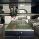
<img src="https://www.gopcba.com/wp-content/uploads/2026/05/Industrial-IOT-PCBA-1.jpg" alt="Heat sink bonding with thermal adhesive on a PCB assembly” />
Why Heat Sink Bonding Uses a Thermal Adhesive
A mechanical fixing holds two surfaces together at a few points, while an adhesive holds them across the whole contact area. For thermal work that difference is decisive, because heat flows through the area and not through the screws.
The adhesive also removes the need for holes in a board that may be densely routed, and it damps vibration at the same time. The trade is that the joint is permanent, so the process has to be right before the parts are brought together.
Surface Preparation Before Bonding
Adhesion depends on the surface the adhesive meets. Solder mask, bare laminate, anodised metal and bare aluminium each behave differently, and contamination from handling, cleaning or a previous process changes the result on all of them.
Preparation normally means cleaning with a compatible solvent and, where the surface allows, a light abrasion, because a surface touched by bare hands is no longer clean whatever it looks like. The same discipline used in coating adhesion testing applies here, because a bond that fails at the interface fails regardless of how good the adhesive is.
Thermal Adhesive Types and Fillers
The common families are epoxy, silicone and urethane, and each trades thermal conductivity against flexibility and cure behaviour. Epoxies are strong and rigid, silicones remain flexible over a wide temperature range, and urethanes sit between the two.
Conductivity comes from the filler, usually a ceramic or a metal powder, and a higher filler load means better heat transfer with a thicker, more abrasive paste. Filled adhesives also settle, so mixing and storage practice changes the properties that reach the joint, and a cartridge stored cold should be brought to room temperature before use.
Bond Line Thickness and Thermal Resistance
Thermal resistance falls as the bond line gets thinner, until the adhesive can no longer fill the gaps between the surfaces. Bond line thickness is therefore a specification, not a result of how hard the parts were pressed together, which makes heat sink bonding a thermal process as much as a mechanical one.
Glass beads or a screen printed pattern are used to hold a defined thickness, and the thickness is verified afterwards by measuring the assembly height or by sectioning a sample. Where the assembly also carries a coating, the cure of the two materials interacts, as described in adhesive cure work.
Dispensing Pattern and Coverage
The pattern has to deliver enough adhesive to fill the intended area without flowing onto components or off the board edge. A dot pattern squeezes out into a continuous layer, while a bead pattern risks trapping air in the middle of the joint.
Dispensing equipment, needle size and the time between dispensing and placement all matter, and the technique shares a great deal with underfill dispensing practice. The volume should be controlled by weight or by a calibrated dispense, not by the appearance of the bead, since a dispense repeated by weight is far more repeatable than one judged by eye.
Cure Schedule and Clamping
The cure schedule sets the final strength and the final thickness at the same time. A slow cure at moderate temperature gives the adhesive time to flow and wet, while a fast cure freezes the joint in whatever shape it had at the start.
Clamping holds the bond line during cure, and the pressure has to be enough to spread the adhesive without squeezing it out completely. Fixtures, weights and vacuum bags all work, provided the pressure is uniform and the parts cannot shift while the adhesive gels, so the fixture should prevent any rotation as the adhesive flows.
Voids, Flow and Component Stress
Air trapped in the adhesive becomes a void, and a void under a hot component raises the local thermal resistance sharply. Voids come from a bead pattern that closes on itself, from a dispensing needle that draws air, and from outgassing during a fast cure. A void in the centre of a large sink costs more performance than the same void at the edge.
Thermal expansion is the other concern. A rigid adhesive on a thin board can bow the assembly as it cures and cool, which stresses nearby solder joints. The measurement work described in board strain measurement shows how much movement the assembly actually sees.
Testing the Bond
The bond is checked by measuring the thermal path and by measuring the mechanical strength. A thermal test compares the component temperature with and without the sink, while a shear or pull test on a sample assembly gives a number that can be trended, and both tests should be run on the same sample population.
Sectioning a cured sample shows the bond line thickness and the void content, and it is the quickest way to confirm that the dispensing and clamping steps did what the recipe intended. Failure mode matters more than the number, since a cohesive failure inside the adhesive is a better result than a clean release from the metal. Thermal design context is set out in PCB thermal design work.
Records and Process Control
The record should carry the adhesive lot, mix and degas details, the dispensed weight, the bond line thickness, the cure schedule, the clamp pressure and the test result. With those fields, a thermal complaint can be traced to a step rather than guessed at, and trending the dispensed weight is the fastest way to spot a drifting dispenser.
Where the process follows a published standard, such as the assembly documents from IPC, that standard should be named in the work instruction together with the acceptance value for the shear strength.

FAQ
How thick should the bond line be? Thin enough for good thermal transfer and thick enough to fill the gap between the surfaces, with glass beads or a printed pattern used to hold the value. The number should be specified and measured rather than left to clamping pressure.
Does clamping pressure increase bond strength? It increases it until the bond line becomes too thin to fill the surfaces, after which the joint loses both thermal and mechanical performance. Uniform pressure within a defined range is the target.
Can a bonded heat sink be removed for rework? Usually by heating the adhesive to its softening range and working the joint apart, with the risk of damaging the board. Where rework is expected, a removable thermal interface rather than an adhesive is the better design choice.