
Creepage And Clearance: Design Rules and Process Limits
Creepage and clearance are the two distances that separate conductors held at different potentials. Clearance is the shortest distance through air, and creepage is the shortest distance along the surface of the insulation. Both have to be large enough that the voltage cannot flash over or track across.
The required distances come from a product safety standard, and they depend on the working voltage, on the pollution degree of the environment and on the material group of the laminate. Getting them wrong is not a performance problem, it is a safety and compliance problem.
Clearance, Creepage And What Each Protects
Clearance protects against a flashover through air, which is a fast breakdown that depends on the voltage and on the air pressure and humidity. Creepage protects against tracking along a surface, which is a slower process driven by contamination and moisture.
Because the mechanisms differ, the two distances are calculated separately and are usually different values. A design satisfies the requirement only when both the air gap and the surface path meet their own minimum figures.
Working Voltage And Overvoltage Category
The working voltage is the voltage that appears across the insulation in normal operation, including any transient the circuit can produce. The overvoltage category describes the transient environment, from a protected low voltage circuit up to a mains supply at the point of entry.
The category is decided by the product standard and by where in the installation the equipment sits. Once the category and the working voltage are known, the tables in the standard give the required distances without any further calculation.
Pollution Degree And Its Effect
Pollution degree describes what can be deposited on the surface. A clean, dry, sealed environment is degree 1, a normal office or laboratory is degree 2, and an industrial environment with condensation or conductive dust is degree 3 or 4.
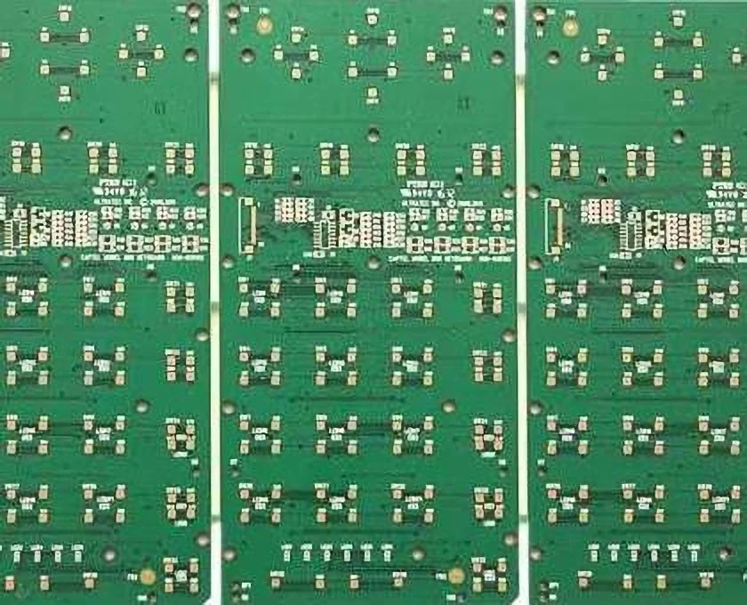
Higher pollution degrees require longer distances, and the increase is substantial. A design that meets its requirement inside a sealed enclosure may need to double its creepage if the same board is used in an unsealed industrial housing. Protecting the surface with a coating is described under conformal coating and board protection.
Using The Tables From The Standard
The tables are indexed by working voltage, pollution degree and material group, and they give a minimum creepage directly. Clearance is looked up from a separate table indexed by working voltage and by the transient the circuit has to withstand.
The material group of the laminate depends on its comparative tracking index, which for standard FR-4 is usually group IIIa. A high performance laminate can move the design into group II, which reduces the required creepage slightly and is sometimes worth the extra material cost.
Slots And Cutouts
A slot cut through the board interrupts the surface path, and the creepage distance is then measured around the slot rather than straight across it. This is a common technique for gaining creepage without increasing the board area.
The slot must be wide enough that the measuring path does not bridge across it, and it must be routed cleanly so that no conductive burr remains. A slot that is too narrow can be bridged by a contamination film and then provides no benefit at all.
Conformal Coating And Potting
A conformal coating can improve the effective pollution degree, because it seals the surface against moisture and contamination. The standard allows a reduction in creepage for a coated assembly, but only when the coating is qualified for the purpose and covers the relevant area completely.
Potting goes further, since the assembly is encapsulated in a solid insulator. The distances can then be calculated using the dielectric strength of the potting compound, which is a different calculation from the surface rules that apply to an uncoated board.
Layout Practice
The practical approach is to place the high voltage section first, in its own area of the board, so that the distances can be satisfied before the low voltage routing is added. Trying to insert the isolation barrier afterwards rarely works without redoing the layout.
The isolation barrier should be marked on every layer, and the layout tool should carry a rule that prevents copper, mask openings or silkscreen from crossing it. Components are usually kept out of the barrier as well, because a component body can reduce the effective distance. The general spacing rules are described under design guidelines for manufacturability.
Verification And Documentation
Verification is by measurement on the fabricated board, using the correct definition of the shortest path, and the results are recorded for the safety file. Measurement on the artwork is a design check, not a substitute for measuring the finished product.
The barrier location, the working voltage and the required distances should all appear on the fabrication and assembly drawings, so that a later revision cannot quietly reduce them. How the requirement reaches the fabricator is described under PCB design and fabrication.
Altitude And Its Effect On Clearance
Air thins with altitude, and thinner air breaks down at a lower voltage. A design that is compliant at sea level can fail its clearance requirement at 2000 metres, which matters for equipment installed in a mountainous region or carried as air cargo.
The standard deals with this by applying an altitude correction factor to the clearance only, since creepage along a surface is not affected in the same way. A product intended for a wide market should state its maximum altitude and apply the correction.

Transient Voltages And Their Source
The transient the insulation has to withstand is not the working voltage but the surge that the installation can deliver. A mains fed product may see a surge of several kilovolts, while a battery powered device inside a metal enclosure sees far less.
Surge suppression devices reduce the transient but do not remove it, and the standard normally requires the distances to be met without relying on a suppressor. Where a suppressor forms part of the protection concept, its failure mode has to be considered as well.
Common Design Mistakes
The most common mistake is to measure creepage along the shortest straight line rather than along the shortest path over the surface, which understates the real distance. A second is to forget that a mask opening or a via in the barrier interrupts the surface path and changes the measurement.
A third is to place a component across the barrier and assume that the component body provides insulation. Most bodies are not qualified as insulation, so the distance then has to be measured around the component rather than through it.
FAQ
Is creepage always larger than clearance? Often, but not always. At high altitude the clearance requirement grows, while at a high pollution degree the creepage requirement grows. Both have to be checked separately for the application.
Does solder mask count as insulation? In most standards it does not, and the distances are measured as though the mask were not present. A conformal coating applied after assembly is treated differently and has to be qualified.
Can a slot be used instead of more space? Yes, and it is a common technique. The slot must be long enough that the path around it exceeds the required creepage, and it must be routed cleanly.