PCB Silkscreen Legend And Clearance Rules
The silkscreen, or legend, is the printed information on a board that a human reads: the reference designators, the polarity marks, the connector pin numbers, the part outlines and the warnings. It is the cheapest layer of the board and the one most often treated as an afterthought, and it is the layer that decides how quickly an assembly can be debugged, how confidently a rework can be done and how many mistakes are made on the line.
This article describes what belongs on the legend, how the clearances are set, how the text is sized for legibility, and what happens to the board when the legend is drawn without regard to the process.
What The Legend Is For
The legend serves three readers. The assembly operator uses it to check that the right part is in the right place and the right way round. The test and rework technician uses it to find a net, a test point or a component without opening the schematic. The end user or the field engineer uses it to identify a connector or a revision. Each of those readers needs a different piece of information, and a legend that carries only the reference designators serves the first of them properly and the others poorly.
Polarity and orientation marks are the most valuable part of the legend, because they prevent a defect rather than merely helping to find one. A diode, an electrolytic capacitor, a connector and a fine pitch package all have an orientation that is not obvious from the outline alone, and a clear mark on the legend is cheaper than an inspection step that checks the same thing.
Clipping, Clearance And What Must Be Removed
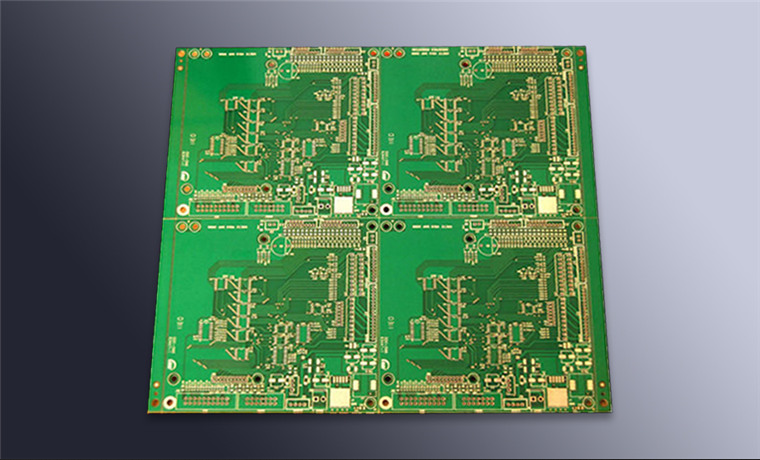
Silkscreen ink is printed on top of the solder mask, so it cannot be placed where mask is absent. Any legend line that falls on an exposed pad, on a test point or on a mask opening is clipped by the fabrication shop, and the clipping is done automatically from the mask layer. The result of ignoring this is a legend with letters that stop halfway through a word and orientation marks that lose their meaning.
The clearance from the mask opening is a design rule, commonly 0.1 to 0.15 millimetres, and the purpose is to allow for the registration tolerance between the legend and the mask. A line placed exactly at the edge of an opening will sometimes overlap it and sometimes leave a gap, and the overlapping case is the one that produces a legend printed onto a pad. The rule is therefore stated as a minimum gap rather than as a target.
Line Width, Height And Readability
Legibility is set by the height of the characters and by the stroke width, not by the font. A minimum character height of about 0.8 millimetres with a stroke of 0.12 to 0.15 millimetres is readable under normal lighting, and a height of 1 millimetre with a stroke of 0.15 to 0.2 millimetres is comfortable. Below 0.6 millimetres the printing becomes unreliable because the ink spreads, and the characters fill in.
The font itself should be a simple sans serif without serifs or fine details. The minimum gap between two strokes of the same character has to be larger than the printing tolerance, or an 8 becomes a 0 and an E becomes an F. Where space is tight, the answer is usually to move the reference designator rather than to shrink the text, and a legend that has been designed with the placement rather than after it has room to do that.

Reference Designators And Assembly
A reference designator should be placed so that it is unambiguous which part it belongs to. Beside the part is better than inside its outline, and inside the outline is better than under it, because a designator that is hidden once the part is placed has no value for inspection. Where a part is dense, the designator is moved to the nearest free area and a leader line is drawn, or the designator is omitted for parts that are visually obvious.
The designator placement is part of the placement planning rather than a separate operation, and the rules that keep the parts themselves clear of each other are described under placement order and pad positioning. The overall set of rules that makes the design manufacturable is collected under manufacturable design guidelines.
Fabrication Consequences
A legend that is drawn over pads creates three problems. The mask is opened over the pad, so the ink has nowhere to print and the shop removes it, which changes the appearance of the board. The ink that is removed may be replaced by an automatic clipping that leaves fragments, and the fragments are then inspected and questioned. And if the ink is printed before the mask is fully cured, it can transfer onto the stencil or the tooling during assembly, which is a contamination source.
A legend that is too dense also affects the printing process. Ink spread is proportional to the ink coverage, and a board with heavy legend coverage needs a different exposure and development than one with light coverage on the same panel. Where two products share a panel and one has a heavy legend, the shop will compromise the parameters, which is a reason to keep the legend economical. The mechanical layer that the outline and the legend share is described under board outline and mounting design.
Verification
Verification is a visual check of the first article against the drawing, plus a design rule check in the layout tool. The check should confirm that no legend exists over a mask opening, that every designator is present and legible, that the polarity marks are correct and that the revision and the part number are printed where they belong.
The design rule check catches the geometric problems, but it cannot catch a wrong polarity mark or a designator that is attached to the wrong part. Those are found by comparing the printed legend with the placement file, which is a short exercise on the first article and impossible to do on a finished assembly. Doing it once, at the start, prevents a whole lot of parts from being placed the wrong way round.
Board Identity, Revision And Warnings
The legend is also where the board identifies itself. A part number, a revision letter and a date code are printed on every board, and they are what makes a complaint traceable. A board without a revision mark cannot be compared with the drawing that describes it, and a board without a part number cannot be matched to its schematic, so both are printed even on a single prototype. The habit becomes valuable the first time two versions of the same board are on the same bench.
Warnings and handling marks belong in the same category. An electrostatic sensitive device symbol, a moisture sensitivity note, a connector keying mark and a maximum voltage mark are all cheap to print and all communicate something that would otherwise be discovered by damaging the board. The place for them is the area that stays visible after assembly, typically beside a connector or along the board edge, and the space for them should be reserved during the layout rather than found afterwards.
FAQ
Should the reference designator be visible after assembly? Ideally it should. A designator that is hidden under the body is of no use to the inspector or to the rework technician, so it is moved outside the part where there is room.
Can silkscreen be printed over a via? It can, provided the via is covered by mask. A tented via can carry legend over it, while an open via will have the ink removed and the legend broken.
What is the minimum text size? About 0.8 millimetres high with a 0.12 millimetre stroke is the practical minimum, and 1 millimetre with a 0.15 millimetre stroke is more comfortable. Anything smaller is likely to be illegible after printing.