PCB V-Cut Panelization: Angles, Tolerances and Spacing
V-cut is the fastest way to hold several boards in one panel and to separate them afterwards. A pair of blades cuts a V shaped groove along both faces of the panel, leaving a thin web of material in the middle, and the individual boards are snapped apart when they are needed.
The method is economical and it leaves a clean straight edge, but it imposes constraints on the layout that are easy to violate. The groove consumes space, it must not pass through copper, and the break applies a bending load that the components near the edge have to survive.
What V-Cut Does
Two rotating blades cut into the top and the bottom of the panel along the same line, each removing a wedge of material. The uncut material that remains is the web, and its thickness decides both the rigidity of the panel and the force required to break the board out.
The groove is straight, so it can only be used on a straight edge. Curved outlines, internal cutouts and boards with an irregular shape need routing, which is why most production panels combine the two methods.

Geometry and the Remaining Web
The blade angle is typically 30 or 45 degrees, and the depth is set so that the remaining web is about one third of the board thickness, with a usable range of roughly 0.25 to 0.8 mm. A thinner web breaks easily but leaves the panel fragile and prone to breaking in the machine.
A thicker web holds the panel together but requires more force to separate, which increases the bending stress on the board and on the components near the edge. The balance is decided by the assembly process: a panel that is depaneled by hand needs a thinner web than one separated by a machine that supports the board.
Tolerances and Depth Control
The position of the groove is controlled by the machine, and it is normally referenced to the panel outline rather than to the artwork. The tolerance is typically around plus or minus 0.1 mm on the remaining web, which translates into a variation in the breaking force and in the appearance of the separated edge.
The groove has to be centred on the cut line. An off centre groove produces a step on one side of the separated board, which can interfere with a card guide or with the fit of a housing. Where the edge is a datum, the groove position is specified and measured rather than left to the machine default.
Panel Layout and Spacing Rules
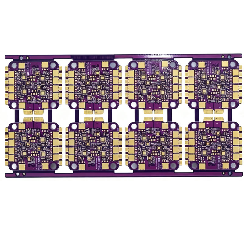
Boards in a V-cut panel share a common edge, so there is no material between them apart from the web. That is what makes the method efficient, and it also means the copper of one board comes close to the copper of the next.
The spacing rules follow from the groove geometry. Copper must be kept clear of the groove by a distance that accounts for the blade angle and the etch tolerance, typically 0.4 mm or more, and no via or plated feature should fall within that band, because the blade will cut into it and expose the barrel.
V-Cut Versus Tab Routing
Tab routing leaves a gap between boards and connects them with small tabs that are routed and then broken or cut. It costs more panel area, but it allows curved outlines, it keeps the boards apart and it lets the tabs be placed where they cause least stress.
V-cut is faster and cheaper and it produces a cleaner edge on a straight line, at the cost of panel area efficiency when the boards have fine features near the edge. The choice is usually made per edge rather than per panel, with the straight edges scored and the rest routed.
Component and Copper Keep-outs
The break applies a bending moment along the groove. That moment is largest at the ends of the board and decays with distance, so the components closest to the edge are the most at risk. Large ceramic capacitors, crystals and any component with a brittle body should be kept away from the break line.
The keep-out applies to copper as well. A plane that runs to the edge of the board will be cut by the groove and can delaminate, and a trace that crosses the break line is severed. Both are avoided by the edge clearance rule, and the rule is worth checking on the finished artwork rather than on the layout alone.
Depaneling Practice
The separation is a process step, not an incidental one. A dedicated depanel machine supports the board on both sides of the groove and applies a controlled force, while manual breaking bends the panel with no support and produces the highest stress on the assembly.
Where the boards are assembled before depaneling, the fixtures and the conveyor have to accommodate the whole panel. The panel stiffness, the size and the position of the tooling holes are all part of the mechanical design, and they are easier to define before the panel is laid out than afterwards.
Inspection and Defects
The recurring defects are a groove that is off centre, a web that is too thin and breaks in the machine, a web that is too thick and tears instead of snapping, and delamination at the edge caused by a blade that is dull or a cut that reaches the copper.
Inspection covers the groove position, the remaining web and the condition of the separated edge. Where the board goes into a card guide or a housing, the edge is also checked for a step, since a groove that is not centred produces a ledge that interferes with the fit.
Design Rules and Specification
State which edges are scored, the blade angle, the remaining web thickness and the clearance from the groove to any copper or component. Where an edge is a mechanical datum, specify the tolerance on the groove position rather than only on the board outline.
gopcb produces V-cut and routed panels with controlled web thickness and edge inspection, and can advise on the panel layout that gives the most boards per panel without putting the edge features at risk.
The economics of panelization are worth a moment. A panel with more boards reduces the fabrication cost per board, but it also increases the risk that a single defect affects a larger area and it makes the panel heavier to handle. V-cut panels are usually laid out with the boards sharing edges, so the utilization is high, and the limiting factor is often the stiffness of the panel through the assembly line rather than the number of boards that will fit. A panel that is too large sags in the printer and a panel that is too small wastes the machine’s capacity, so the size is chosen with the assembly equipment in mind as well as the fabricator’s standard panel format.
FAQ
How thick should the remaining web be? Around one third of the board thickness, typically between 0.25 and 0.8 mm. A thinner web breaks easily but makes the panel fragile.
Can V-cut be used with a curved outline? No. The groove is straight, so any curved edge has to be routed instead. Most panels combine the two processes.
Why does the separated edge sometimes chip? Usually because the groove reached the copper or because the web was too thick for the breaking method. Both are process issues that show up as delamination or a rough edge.
Related reading: PCB routing precision, board outline and mounting design, PCB manufacturing tolerances, and PCB router bits and depaneling.