Press Fit Connector Hole Design For Backplanes
A press fit connector is held in a plated hole by the elastic deformation of its own pin rather than by solder. The pin is wider than the hole, and the compliant section compresses as it enters, then pushes back against the plating to form a gas tight contact. Because there is no solder, the reliability of the joint depends entirely on the geometry of the hole and on the properties of the plating inside it.
This article covers how the contact is formed, how the hole is dimensioned, what the plating has to do, and how the result is verified in production.
How The Contact Is Formed
The compliant part of the pin is usually an eye of the needle, a tube with a slot along its length that allows the diameter to reduce. Other designs use a solid pin with a shaped cross section that flexes, or a pair of spring arms. Whichever form is used, the pin enters the hole with an interference of a few hundredths of a millimetre, and that interference is what generates the contact force.
The force has to be high enough to break through the oxide on the plating and to cold weld a small area of metal to metal contact, and low enough that the pin does not damage the hole or buckle. Because the contact area is small and the force is concentrated, the joint is gas tight and does not corrode, which is why press fit connections survive environments that would degrade a soldered joint. The result is also repairable in one direction only: a pin may be pressed out and a new one pressed in, but each insertion enlarges the hole slightly, and the number of permitted reworks is stated by the connector manufacturer.
Dimensioning The Hole
The finished hole diameter is the single most important number on the fabrication drawing. It is the drilled diameter plus the plating thickness on both walls, so the drawing normally states the finished diameter and the plating thickness separately and leaves the drill size to the shop. A hole that is too small raises the insertion force, damages the pin and can crack the barrel; a hole that is too large reduces the interference and the contact force, and the joint becomes intermittent under vibration.
The tolerance on the finished hole is tighter than for a normal component hole, and it has to be held across the whole panel rather than on average. Drill wear, plating thickness variation and laminate movement all contribute, and the combined variation is what the connector manufacturer’s specification accounts for. Where the panel is large, the variation across the panel is often greater than the variation between panels, so samples are taken from several positions rather than from the centre alone. Plating defects that would be acceptable elsewhere are not acceptable here, as described under copper plating defects prevention.
What The Plating Has To Do
The plating is the material that the pin actually contacts, and it has to be thick enough and ductile enough to survive the insertion without cracking or being pushed aside. A thin plating is punched through by the pin, exposing the copper beneath, and the exposed edge corrodes. A brittle plating cracks at the point of contact and the fragments become an intermittent connection. The usual requirement is a plating thickness at the upper end of what the process can hold, with a ductility that allows the pin to deform it rather than break it.
Plating in the hole must also be uniform around the circumference and along the barrel. A barrel that is thinner on one side, which is common in a hole that is not perfectly centred in the pad, gives a contact whose force depends on the direction the pin entered. Where the connector is inserted by machine, the direction is controlled; where it is inserted by hand, it is not, and a directional joint is a source of field failures that are hard to reproduce. The same barrel quality concerns apply as in blind and buried via selection, where the geometry of the hole governs the plating result.
Insertion And Retention Force
Insertion force is the practical measurement that ties the whole system together. Each pin contributes a force, and the total for a connector with hundreds of pins is enough to require a press. The force per pin is specified as a range, and a value below the range means the hole is too large or the plating is too thin, while a value above it means the hole is too small or the pin is misaligned. Measuring the force on a sample connector per panel is a cheap and direct check on the whole process.
Retention force is measured by pulling the connector after insertion. It is normally higher than the insertion force, because the pin has to be reversed past the point of maximum interference, and it is the property that resists vibration. Both forces are temperature dependent, and both change if the board is reflowed after the connector is pressed, which is why the sequence of assembly steps is fixed in the process specification rather than chosen by the line.

Board Support And Mechanical Design
A press applies a large force to the board, and the board has to be supported so that it does not flex under that force. Flexing opens the hole that is being loaded, reduces the interference locally, and can crack the plating around a neighbouring hole. Press tools therefore support the board close to the connector footprint, and the layout keeps other components and their joints out of the region that will be loaded.
The connector also imposes a mechanical load on the board in service, especially where it carries a cable. The mounting hardware around a press fit connector, and the board fixings that react the cable load, belong with the general arrangement described under board outline and mounting design. A press fit connector that is expected to take a cable load without any additional support will eventually work its hole open, and the intermittent contact that follows is difficult to trace.
Verification In Production
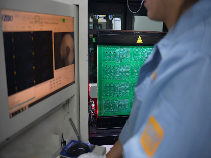
Verification combines three measurements. The finished hole diameter is checked on a sample of holes per panel, using a pin gauge or an optical measurement rather than a drill report. The plating thickness in the hole is checked by microsection of a coupon that travelled with the panel. The insertion force is checked with a sample connector or with a force gauge on representative pins, and the retention force is checked on the same sample afterwards.
Continuity of the inserted connector is checked electrically, but a continuity check only finds a joint that is already open, and it will not find one that has marginal contact. That is why the mechanical measurements carry the weight and the electrical test is a confirmation rather than the main control. Building a press fit product successfully means controlling a hole diameter to a tolerance far tighter than the rest of the board, and accepting that this is a machining problem as much as a circuit one. The overall design rules that surround such a requirement are set out under design guidelines for manufacturability and in the prototype programme described under multilayer prototype requirements.
FAQ
Can a press fit hole be soldered as well? It can be, and some designs specify both, but soldering does not improve a correct press fit and it prevents the rework that the press fit allows. The choice should be made once, on the basis of the service environment and the repair strategy.
How many times may a connector be reworked? The connector manufacturer states a limit, usually one or two press out and press in cycles, because each cycle enlarges the hole and reduces the contact force. Exceeding the limit quietly converts the joint into a marginal one.
Why is the finished hole diameter specified instead of the drill size? Because the plating thickness is also specified and the two together determine the hole the pin actually sees. Leaving the drill size to the shop lets the fabricator reach the finished diameter with its own plating process.