Hand Soldering A QFN: Step By Step
A QFN package has no leads to solder. Its connections are flat pads on the underside of the body, arranged around the perimeter, with a large exposed pad in the centre that serves as both the thermal path and, usually, the ground connection. Everything that has to be joined is underneath the part, which is why the package is so compact and why hand soldering it is regarded as difficult.
This article sets out a repeatable procedure for soldering one by hand, the tools that make it reliable, and the board features that decide whether it is possible at all.
The method described here uses hot air with a small amount of solder paste, which is the approach most likely to succeed on a first attempt without rework.
Why The Package Is Different
On a conventional leaded package the solder joint is visible from the side and can be touched up with an iron. On a QFN the joint is a fillet between a pad on the board and a pad on the body, both of which are hidden once the part is placed. The only access is from the side, where a properly formed fillet can just be seen at the edge of the body if the pad extends slightly beyond it.
The exposed pad changes the thermal behaviour as well. It is a large area of copper in the centre of the footprint, and it has to be soldered for two reasons: it carries heat out of the die into the board, and it often provides the ground connection. Soldering only the perimeter pads leaves the device thermally isolated and, in many circuits, electrically incomplete.

Tools And Preparation
The tools are ordinary. Magnification, either a stereo microscope or a good loupe, is essential because the joints cannot be inspected otherwise. Tweezers long enough to keep the fingers away from the hot air are needed, along with a hot air station with a nozzle matched to the package size, a fine tipped iron for touch up, solder paste in a syringe, flux, and a solvent for cleaning. A preheater underneath the board is helpful on a multilayer board because it reduces the air temperature required.
Preparation begins with the board. The pad array should be clean and free of oxidation, which normally means cleaning it and, on a board that has been stored, removing any oxide that has formed. The paste should be at room temperature and mixed, since a cold paste does not dispense evenly.
Applying The Solder Paste
Paste is applied to the pads and to the exposed pad, and the quantity is the part that is most often got wrong. Too little and the joint does not form; too much and the surplus is pushed out when the part settles and bridges between adjacent pads. A thin, even layer is all that is required, and a stencil or a dispense tip that gives a consistent deposit is better than free hand application.
Some practitioners apply the paste to the underside of the component instead, which has the advantage of putting it exactly where the pads are. Either method works provided the volume is controlled, and the tackiness of the paste also helps to hold the part in position before reflow. The pad and stencil geometry on the board determines how much paste a given aperture delivers, which is a design decision rather than a bench one.

Placing And Reflowing
The part is placed with tweezers, aligned to the outline printed on the board rather than to the pads underneath, and then checked with magnification. A slight rotation is easier to correct after reflow than a lateral offset, because the surface tension of the molten solder tends to pull a well placed part into alignment while it cannot correct a part that is a full pad out of position.
Heat is then applied with hot air, moving the nozzle in a slow circle over the package so that the whole body heats evenly. Watching the surface is the guide: when the solder paste turns liquid and shiny, the joints are forming, and a small settling movement of the body is a good sign. Directing the air at one spot will overheat that corner and blow the part sideways, so the motion matters as much as the temperature. A preheated board allows a lower air setting, which reduces the risk of damaging the body, and it is the single change that makes the largest difference on a board that sinks heat away quickly.
Inspecting And Cleaning
After the board cools, the joints are checked from the side. A correctly formed fillet is visible at the edge of the body, and on a fine pitch part it appears as a small bright band on each pad. Defects appear as a dark gap, an uneven fillet or a bridge between adjacent pads. Excess solder that has been expelled from under the body is removed with a fine iron and flux, and the area is cleaned afterwards.
Because the joints cannot be seen directly, a part that looks correct from the side may still have an incomplete connection under the centre. Where the thermal performance is critical, an X-ray inspection is the only way to confirm that the exposed pad is attached, and it is worth doing on the first board of a new design. The geometry that makes the part easy to place also makes it easier to inspect.
What The Board Has To Get Right
No amount of bench skill will compensate for a poor footprint. Each pad should be sized so that a small fillet is possible at the outer edge, which means extending slightly beyond the body outline. The exposed pad should be divided by the solder mask into a pattern of smaller openings rather than left as one large area, because a single large opening allows the part to float on a pool of molten solder and tilt.
Thermal vias under the centre pad have to be treated deliberately. An open via will wick solder away from the joint and leave voids, so the options are to tent the via on the opposite side, to plug it, or to use a via in pad structure that is filled and plated. Whichever is chosen, it has to be stated, because the assembler cannot fix it by adding more paste. gopcb builds boards with QFN footprints, thermal vias and mask defined centre pads as the design requires, and reviews the footprint before the panel is released.
FAQ
Can a QFN be soldered with an iron alone? Not reliably for the centre pad, because the iron cannot reach it. Hot air or a reflow oven is the practical method, with the iron used only for touch up.
Why does the part shift during reflow? Usually too much paste, which lets the body float, or air directed at one corner. Reducing the paste volume and keeping the nozzle moving usually fixes it.
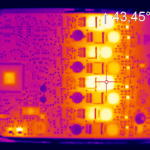
How can I tell whether the centre pad is attached? From the side it is impossible. X-ray, or a thermal measurement that reveals abnormal heating, is the way to confirm it.