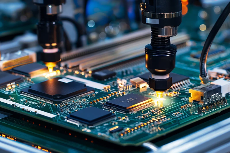
Introduction
A Rigid-Flex PCB combines the structural stability of a rigid circuit board with the flexibility of a flexible circuit. This hybrid construction allows electronic designers to integrate rigid mounting areas with flexible interconnect sections within a single PCB structure.
By reducing the need for separate cables, connectors, and wiring harnesses, rigid-flex technology can help create smaller, lighter, and more reliable electronic products. It is particularly valuable where circuit boards must fit into irregular mechanical spaces, withstand vibration, or accommodate controlled bending.
Modern rigid-flex applications span medical electronics, aerospace and defense, automotive systems, industrial automation, telecommunications, consumer electronics, robotics, and wearable devices. Successful production, however, requires careful consideration of materials, layer stack-up, bend radius, impedance, thermal performance, manufacturing tolerances, and assembly requirements.
For projects requiring advanced fabrication technologies, PCB Manufacturing can support rigid, flexible, multilayer, HDI, high-frequency, and rigid-flex circuit requirements.
What Is a Rigid-Flex PCB?

A rigid-flex PCB is an integrated circuit board that combines rigid PCB sections with flexible circuit sections. The flexible areas are commonly constructed with polyimide-based materials and copper conductors, while rigid sections may use FR-4 or other suitable rigid PCB materials.
Unlike conventional electronics that connect separate rigid and flexible boards with cables or connectors, a rigid-flex design integrates the electrical connection into one continuous PCB structure.
This construction provides several important advantages:
- Rigid sections provide mechanical support for components and connectors.
- Flexible sections allow controlled bending and three-dimensional routing.
- Integrated interconnections reduce the number of cables and connectors.
- The overall assembly can become smaller, lighter, and more reliable.
- The PCB can conform to complex product geometries.
The flexible section should not simply be treated as a thinner rigid PCB. Its copper construction, material properties, layer count, bend direction, bend radius, and transition structure all have a direct influence on reliability.
Rigid PCB vs. Flexible PCB vs. Rigid-Flex PCB
Understanding the differences between rigid, flexible, and rigid-flex circuit boards is important when selecting the appropriate technology.
Rigid PCB
A rigid PCB uses a solid, non-flexible substrate, most commonly FR-4.
Key characteristics:
- Provides strong mechanical support.
- Maintains a fixed physical shape.
- Suitable for conventional electronic assemblies.
- Generally offers a lower manufacturing cost.
- Widely used in industrial, consumer, power, communication, and control electronics.
Rigid PCBs are an effective choice when the product does not require bending or three-dimensional circuit routing.
Flexible PCB
A flexible PCB uses a flexible substrate, commonly polyimide, that allows the circuit to bend or fold.
Key characteristics:
- Lightweight and thin.
- Can conform to curved or irregular structures.
- Suitable for space-constrained products.
- Can replace some wires and connectors.
- Useful for applications requiring static or dynamic flexing.
For projects requiring flexible circuit fabrication and assembly, Flex PCB Assembly provides a suitable manufacturing option for flexible and rigid-flex circuit applications.
Rigid-Flex PCB
A rigid-flex PCB combines both technologies into one integrated structure.
Key characteristics:
- Rigid sections provide structural support.
- Flexible sections provide controlled bending.
- Fewer cables and connectors may be required.
- Supports compact three-dimensional packaging.
- Can improve interconnection reliability.
- Suitable for complex and space-constrained electronics.
Although rigid-flex boards generally cost more to manufacture than conventional rigid PCBs, the reduction in connectors, cables, assembly steps, and mechanical complexity can provide significant system-level benefits.
Advantages of Rigid-Flex PCBs
Reduced Space and Weight
One of the most important advantages of rigid-flex technology is its ability to reduce the space and weight associated with traditional wiring systems.
By integrating flexible interconnects directly into the PCB, designers can eliminate some cables, connectors, and additional mechanical components. This is particularly useful in portable electronics, medical devices, aerospace equipment, automotive electronics, and wearable products.
Improved Mechanical Flexibility
The flexible sections can be routed through compact or irregular mechanical structures. This allows the circuit to follow product contours and reach locations that would be difficult to access with a conventional rigid PCB.
The appropriate bend radius depends on the substrate material, copper thickness, layer count, stack-up, and whether the application involves static or repeated dynamic bending.
Smaller Electronic Products
Rigid-flex technology makes it possible to use internal product space more efficiently.
Replacing cable assemblies with integrated flexible sections can reduce the overall package volume and simplify three-dimensional product design. This is especially valuable for smartphones, cameras, medical equipment, wearable devices, automotive electronics, and compact industrial products.
Improved Interconnection Reliability
Every additional connector, cable, or soldered interconnection can introduce another potential failure point.
A properly designed rigid-flex PCB reduces the number of interconnection points while providing a continuous electrical path between rigid sections. This can improve resistance to vibration, mechanical stress, and thermal cycling when the board is properly designed for the application.
Simplified Assembly
Rigid-flex boards can reduce the number of individual components required for interconnection.
Instead of installing multiple boards and connecting them with separate cables, manufacturers can assemble a more integrated circuit structure. This can simplify assembly, reduce wiring errors, and improve manufacturing consistency.
Types of Rigid-Flex PCBs
Rigid-flex circuits can be categorized according to their conductive layers, stack-up structure, and mechanical construction.
Single-Sided Rigid-Flex PCB
A single-sided structure uses one conductive layer in the applicable flexible or rigid-flex circuit section.
It is suitable for relatively simple circuit designs with lower interconnection density and limited electrical complexity.
Advantages include:
- Simple construction
- Lower relative manufacturing cost
- Suitable for straightforward circuits
- Useful where limited flexibility is required
Double-Sided Rigid-Flex PCB
A double-sided rigid-flex structure uses conductive layers on both sides of the flexible circuit section.
It provides more routing space and supports greater circuit complexity than a single-sided construction.
Typical applications include consumer electronics, medical equipment, industrial electronics, and compact electronic assemblies.
Multilayer Rigid-Flex PCB
Multilayer rigid-flex PCBs integrate multiple conductive layers into a more sophisticated rigid-flex stack-up.
They are suitable for high-density and high-performance applications where routing space is limited.
Common applications include:
- Aerospace electronics
- Medical equipment
- Advanced industrial systems
- High-speed communication equipment
- Automotive electronics
- Defense electronics
Multilayer structures provide greater routing capacity but require tighter control of lamination, registration, drilling, impedance, and mechanical transition areas.
HDI Rigid-Flex PCB
HDI rigid-flex technology combines high-density interconnect structures with flexible and rigid PCB sections.
Microvias, fine traces, and advanced layer structures can be used to accommodate high component density in compact products.
This technology is particularly useful when a product requires both sophisticated routing and three-dimensional mechanical integration.
Rigid-Flex PCB with Reinforcement
Additional stiffeners or reinforcement structures may be used to improve mechanical strength in selected areas.
Reinforcement can be useful around connectors, component mounting areas, termination regions, and other locations subject to mechanical stress.
Rigid-Flex PCB Design Considerations
Successful rigid-flex manufacturing begins with a design that considers electrical, mechanical, thermal, and manufacturing requirements simultaneously.
Bend Radius
Bend radius is one of the most important design parameters.
A bend radius that is too small can place excessive mechanical stress on copper traces, dielectric materials, and transition areas. The appropriate value depends on the number of flexible layers, copper thickness, material construction, and whether the flex area is bent once or repeatedly.
Static vs. Dynamic Bending
Designers must determine whether the flexible section will experience:
- One-time forming
- Occasional repositioning
- Repeated dynamic bending
- Continuous mechanical movement
Dynamic applications generally require more conservative mechanical design than static applications.
Layer Stack-Up
The stack-up should clearly define:
- Rigid layers
- Flexible layers
- Copper thickness
- Dielectric materials
- Adhesive structures
- Coverlay
- Stiffeners
- Impedance structures
- Via construction
A well-designed stack-up improves both electrical performance and manufacturing consistency.
Copper Thickness
Copper thickness affects electrical resistance, current capacity, thermal behavior, and mechanical flexibility.
Thicker copper may improve current-carrying capability but can reduce flexibility. Therefore, copper selection must balance electrical requirements with mechanical requirements.
Rigid-to-Flex Transition
The transition between rigid and flexible sections is a critical area of the design.
Trace routing, copper distribution, coverlay, adhesive structures, stiffeners, and mechanical clearance must be carefully controlled to minimize stress concentration.
Signal Integrity and EMI
High-speed rigid-flex designs require careful attention to signal integrity.
Designers should consider:
- Controlled impedance
- Differential pair routing
- Ground reference continuity
- Return-current paths
- Crosstalk
- EMI shielding
- Layer transitions
- Via structures
The flexible region should be incorporated into the overall signal-integrity strategy rather than treated as an isolated section.
For projects requiring advanced stack-up, impedance, and manufacturability analysis, PCB Design & Layout services can help identify potential design issues before fabrication.
Thermal Management
Rigid and flexible sections can have different thermal characteristics. High-power components should therefore be positioned and thermally managed carefully.
Thermal vias, copper areas, heat-spreading structures, and suitable materials may be required depending on the application.
Component Placement
Components should generally be concentrated in rigid sections wherever possible.
Flexible areas are primarily intended for interconnection and controlled movement. Placing heavy or mechanically sensitive components in flex regions can increase stress and reduce long-term reliability.
How Are Rigid-Flex PCBs Manufactured?
Rigid-flex manufacturing combines processes used in rigid and flexible PCB fabrication. Because different materials and mechanical structures are integrated into one product, process control is especially important.
1. Material Selection
The first step is selecting materials according to electrical, mechanical, thermal, and environmental requirements.
Flexible sections commonly use polyimide-based substrates and copper foil. Rigid sections may use FR-4, high-TG materials, or other specialized laminates.
Material selection should consider:
- Operating temperature
- Flexibility
- Copper adhesion
- Dielectric properties
- Thermal expansion
- Signal integrity
- Environmental reliability
2. Layer Preparation and Lamination
The required rigid and flexible layers are prepared according to the specified stack-up.
Controlled lamination parameters are essential to achieve reliable bonding while maintaining registration between different material structures.
Temperature, pressure, time, and material compatibility must be carefully controlled.
3. Drilling
Mechanical drilling and laser drilling can be used depending on the hole size, layer structure, and design requirements.
Accurate drilling is necessary for:
- Through-holes
- Vias
- Interlayer connections
- Component holes
- Microvias
Hole-wall quality, registration, debris removal, and dimensional accuracy must be controlled during this stage.
4. Copper Plating
After drilling, copper is deposited onto the required surfaces and hole walls to establish electrical connections between layers.
Plating thickness and coverage must be carefully controlled to meet electrical and reliability requirements.
5. Circuit Imaging and Etching
The circuit pattern is transferred to the copper surface using imaging and photolithographic processes.
Unwanted copper is then removed through controlled etching, leaving the required conductive traces and pads.
Trace width, spacing, registration, and conductor geometry must remain within the specified manufacturing tolerances.
6. Solder Mask and Coverlay
Rigid sections commonly use solder mask, while flexible areas may use coverlay or other flexible-circuit protection structures.
These protective layers help protect conductors from contamination, oxidation, mechanical damage, and accidental solder bridging.
7. Surface Finish
Exposed copper pads receive a suitable surface finish to improve solderability and protect the copper from oxidation.
Common options include:
- ENIG
- HASL
- OSP
- ENEPIG
The appropriate finish depends on component requirements, assembly technology, environmental conditions, and product specifications.
8. Silkscreen and Identification
Identification markings can be applied to provide:
- Component reference designators
- Polarity information
- Assembly instructions
- Traceability information
- Product identification
Clear markings can simplify assembly and inspection.
9. Electrical Testing and Inspection
Before shipment, rigid-flex PCBs should undergo appropriate inspection and electrical testing.
Typical quality-control procedures may include:
- Automated Optical Inspection (AOI)
- Dimensional inspection
- Hole inspection
- Copper thickness verification
- Electrical continuity testing
- Insulation testing
- Visual inspection
- Surface-finish inspection
For comprehensive production controls, Quality Management procedures can help ensure PCB fabrication and assembly remain consistent with defined technical requirements.
Rigid-Flex PCB Assembly
After fabrication, rigid-flex PCBs can be assembled using SMT, through-hole, or mixed-technology processes.
The assembly process may include:
- Solder paste printing
- Solder paste inspection
- Component placement
- Reflow soldering
- Through-hole insertion
- Selective or wave soldering
- AOI inspection
- X-ray inspection
- Electrical testing
- Functional testing
Because flexible sections can be mechanically sensitive, suitable fixtures and handling procedures should be used to prevent excessive bending or stress during assembly.
For complete manufacturing and assembly requirements, PCB Assembly solutions can integrate PCB fabrication, component sourcing, SMT, THT, inspection, and testing.
Quality Control for Rigid-Flex PCBs
Rigid-flex PCBs require comprehensive quality control because several different materials and processes are integrated into one product.
A professional quality-control program may include:
- Engineering review
- DFM analysis
- Material verification
- Stack-up verification
- Dimensional inspection
- Copper thickness inspection
- Hole and via inspection
- AOI
- X-ray inspection where required
- Electrical testing
- Solderability verification
- Assembly inspection
- Functional testing
- Final inspection
Production documentation should clearly define material specifications, layer construction, copper thickness, surface finish, tolerances, bend requirements, and special processing requirements.
Manufacturers with established engineering and quality systems can identify potential production risks before fabrication begins.
Applications of Rigid-Flex PCBs
Medical Electronics
Medical equipment often requires compact electronics, reliable interconnections, and efficient use of internal space.
Rigid-flex PCBs can be used in:
- Diagnostic equipment
- Monitoring systems
- Portable medical devices
- Medical instruments
- Wearable healthcare products
Their ability to fit complex mechanical structures makes them useful where conventional cable assemblies are difficult to integrate.
Aerospace and Defense
Aerospace and defense electronics place high demands on weight, space utilization, reliability, vibration resistance, and environmental performance.
Rigid-flex PCBs can reduce wiring complexity while supporting compact system architectures.
Material selection, manufacturing controls, inspection, and reliability testing should be matched to the specific application requirements.
Automotive Electronics
Automotive systems increasingly require compact electronics that can operate in environments involving vibration, temperature variation, and limited installation space.
Potential applications include:
- Instrument clusters
- Infotainment systems
- ADAS electronics
- Camera systems
- Sensor modules
- Control systems
Industrial Equipment
Industrial machines frequently contain motors, sensors, controllers, moving mechanisms, and confined installation spaces.
Rigid-flex circuits can provide reliable connections between fixed and moving sections while reducing the need for separate wiring harnesses.
Applications include:
- Industrial automation
- Robotics
- Motion-control systems
- Sensors
- Industrial instruments
Consumer Electronics
Consumer electronics require increasingly compact designs with higher functionality.
Rigid-flex PCBs can be used in:
- Smartphones
- Cameras
- Wearable devices
- Headphones
- Portable electronics
- Smart devices
Their combination of rigid mounting areas and flexible interconnections makes them well suited to modern compact product architectures.
Why Choose Professional Rigid-Flex PCB Manufacturing?
Rigid-flex fabrication requires more than standard PCB manufacturing. The manufacturer must understand both electrical circuit fabrication and the mechanical behavior of flexible materials.
A capable manufacturing partner should provide:
- Engineering and DFM support
- Rigid and flexible PCB fabrication
- Rigid-flex manufacturing
- Prototype production
- Volume production
- Material sourcing
- Precision drilling and plating
- Electrical testing
- AOI and X-ray inspection
- PCB assembly
- Technical support throughout production
GOPCBA provides integrated PCB manufacturing and assembly services, including rigid, flexible, rigid-flex, HDI, multilayer, high-frequency, high-TG, heavy-copper, and other specialized PCB technologies.
Rigid-Flex PCB Manufacturing Capabilities
Modern rigid-flex projects may require advanced manufacturing capabilities such as multilayer construction, controlled impedance, microvias, fine-pitch routing, and complex rigid-to-flex transitions.
A manufacturer should evaluate the complete design before production, including:
- Gerber files
- Stack-up drawings
- Drill files
- Mechanical drawings
- BOM
- Material requirements
- Surface finish
- Flex-zone specifications
- Bend requirements
- Electrical specifications
GOPCBA’s published PCB manufacturing capabilities include multilayer, HDI, controlled-impedance, flexible, rigid-flex, high-frequency, heavy-copper, and other advanced PCB technologies.
Get a Rigid-Flex PCB Quote
Rigid-flex PCB technology is an effective solution for electronic products that require compact dimensions, reduced wiring, mechanical flexibility, and reliable electrical interconnections.
Successful results depend on careful engineering from the beginning of the project. Material selection, stack-up design, bend radius, copper construction, rigid-to-flex transitions, manufacturing tolerances, assembly methods, and testing requirements should all be evaluated before production.
To begin a project, prepare your:
- Gerber or ODB++ files
- PCB stack-up information
- Drill files
- Fabrication drawings
- BOM
- Component information
- Surface-finish requirements
- Mechanical drawings
- Special electrical or environmental requirements
For technical consultation, prototype development, or production requirements, Contact GOPCBA to discuss your rigid-flex PCB project. GOPCBA’s contact page provides engineering and manufacturing support for PCB fabrication and assembly projects.
Frequently Asked Questions
What is a Rigid-Flex PCB?
A rigid-flex PCB integrates rigid circuit-board sections and flexible circuit sections into one PCB structure. It provides mechanical support where components need to be mounted while allowing controlled flexibility where the circuit needs to bend or conform to a product structure.
What are Rigid-Flex PCBs used for?
Rigid-flex PCBs are commonly used in medical electronics, aerospace and defense systems, automotive electronics, industrial equipment, robotics, wearable devices, cameras, smartphones, telecommunications equipment, and other compact electronic products.
What are the main advantages of Rigid-Flex PCBs?
The primary advantages include reduced weight and space, fewer cables and connectors, improved three-dimensional packaging, greater mechanical flexibility, simplified interconnections, and potentially improved system reliability.
What materials are used in Rigid-Flex PCBs?
Flexible sections commonly use polyimide-based materials with copper conductors, while rigid sections often use FR-4 or other rigid PCB laminates. The final material selection depends on electrical, mechanical, thermal, environmental, and reliability requirements.
Can Rigid-Flex PCBs be assembled with electronic components?
Yes. Rigid-flex boards can be assembled using SMT, through-hole, or mixed-technology assembly processes. However, the flexible sections require appropriate handling, support fixtures, and process controls to prevent excessive mechanical stress during assembly.
What files are required for Rigid-Flex PCB manufacturing?
Typical production documentation includes Gerber or ODB++ files, drill files, PCB stack-up information, fabrication drawings, BOM, material specifications, surface-finish requirements, mechanical drawings, and any special electrical or environmental requirements.
Conclusion
Rigid-flex PCB technology combines the structural strength of rigid circuit boards with the flexibility of flexible circuits, providing an effective solution for increasingly compact and complex electronic products.
By integrating rigid and flexible sections into a single PCB, designers can reduce cables and connectors, improve space utilization, simplify three-dimensional packaging, and potentially increase interconnection reliability.
However, rigid-flex manufacturing requires careful engineering. Bend radius, material selection, copper thickness, stack-up, rigid-to-flex transitions, signal integrity, thermal management, assembly handling, and quality inspection must all be considered together.
With the right manufacturing partner and a design optimized for manufacturability, rigid-flex PCBs can provide a reliable foundation for next-generation medical, aerospace, automotive, industrial, consumer, and communication electronics.