SMT Assembly Line: Stage by Stage from Stencil to AOI
An SMT line is a sequence of machines whose settings have to agree with one another and with the board being built. Following the flow stage by stage is useful not only for operators but for designers, because every station imposes a requirement on the board. The stencil imposes a paste requirement, the placement machine imposes a fiducial and rail requirement, the oven imposes a thermal mass requirement, and the inspection equipment imposes a contrast requirement. This walkthrough follows a panel from bare board to inspected assembly.
Why Surface Mount Replaced Through-Hole Insertion
Surface mount technology attaches components to pads on the surface of the board rather than inserting leads through holes and soldering them on the reverse side. The change allowed production to become faster and more automated, and it allowed components to become smaller, thinner and mechanically more robust. A modern board may carry hundreds of surface mount parts and only a handful of through-hole components, usually connectors or power devices that need mechanical strength.
Materials, Program and Feeder Setup
The line starts with material preparation. Components are loaded onto feeders according to the bill of materials, and each feeder is inserted into a defined slot on the placement machine. Which part number goes into which slot is fixed by the program the process engineer prepared, and the assembly will not be built correctly if a reel is inserted in the wrong position. While the material is being prepared, the boards are staged on carriers.
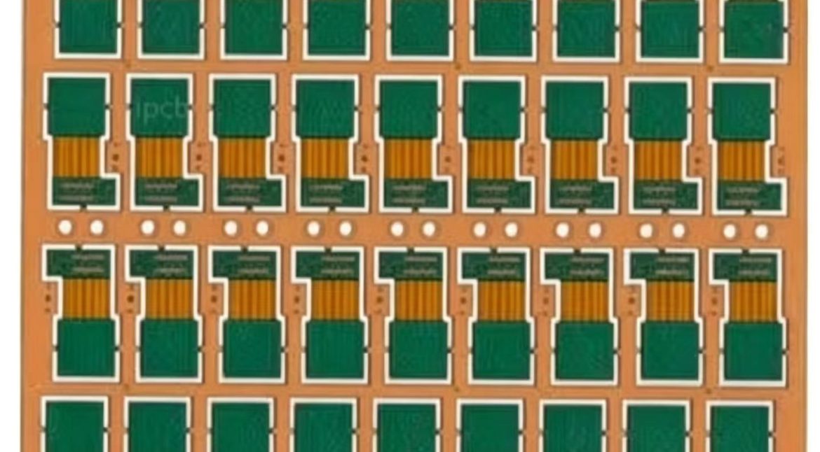
The carrier, made from a high-temperature material, holds the boards through the entire process and returns to the start of the line once the finished assemblies are unloaded. Large boards may be carried individually, while small boards are usually combined into a panel so the line can handle them efficiently. That is why panelization decisions taken at the design stage show up here, in the setup time of the line.
Solder Paste Printing
The first process station prints solder paste. A stainless steel stencil is aligned over the board, and its apertures correspond to the pads that need paste. A squeegee then moves across the stencil, filling each aperture with paste whose volume is set by the aperture area and the stencil thickness, and the paste stays on the pad when the stencil is lifted away.
Printing is where most soldering defects originate, and the controlling parameters are stencil thickness, aperture design, squeegee pressure and speed, separation speed and paste rheology. The area ratio, the ratio of aperture area to aperture wall area, determines how cleanly the paste releases; below a certain value the paste sticks to the stencil walls instead of transferring to the pad. Pad positioning and placement order interact with that ratio, which is why footprint design is a soldering decision as much as a routing one.
Component Placement
The board then moves to the placement machine, where heads pick components from the feeders and place them on the paste-covered pads. The machine uses the fiducial marks on the board or panel to establish its coordinate system, then moves each head to the programmed position. Placement speed is far beyond human capability, and placement accuracy is typically a small fraction of the component size, which is what makes tiny passives and fine-pitch area arrays practical at all.
Placement is also where vision systems earn their place. Modern machines inspect each component as it is picked, rejecting parts with damaged leads or incorrect orientation, and they check the placement position afterwards. This internal inspection is the first quality gate on the line.
Between printing and reflow, the assembly is held only by the tackiness of the paste, so conveyor transfer and handling must avoid vibration.
Reflow Soldering
The reflow oven is the last process station. Its zones raise the board through a controlled profile: preheat, soak, reflow and cooling. During the reflow stage the paste melts, wets the pad and the component termination, and forms the intermetallic joint. The reflow profile has to bring every joint above the alloy liquidus for long enough to wet properly, without exceeding the thermal limits of the components or the laminate.
Thermal mass is the complication. A board carrying a heavy connector and a large ground plane heats unevenly, and a profile that suits the small passives may leave the heavy joints cold. Profiling with thermocouples attached to representative joints on a real assembly, and repeating the exercise whenever the board or the oven changes, is the only reliable way to confirm the profile. The causes of component shift during reflow are closely related to how the profile and the paste handle that uneven heating.
Cooling
Cooling is a controlled stage, not a pause. The cooling rate determines the grain structure of the joint: a joint cooled too slowly forms a coarse structure with lower fatigue resistance, while cooling too quickly can produce thermal shock and cracked components. The cooling zone is normally part of the same oven, with its own set points and its own effect on the profile.
Inspection
After cooling, the assembly passes to automated optical inspection, which compares the board against a reference image and looks for missing components, wrong orientation, insufficient or excessive solder, bridging and displacement. Optical inspection cannot see joints under area array packages, so X-ray inspection is used where those parts are present.
Optical inspection is followed by a visual check under magnification, which catches conditions the machine was not programmed to detect. This should not be the first time the board has been examined, because earlier detection is cheaper, and the quality characteristics defined at the design stage determine how much the inspection stages will have to find.

From there the assemblies are unloaded into trays, but the feedback loop is what turns a sequence of machines into a controlled process.
Process Control and Feedback
Each stage produces data. Print inspection measures paste volume, placement machines record their own accuracy, and the reflow oven logs its profile. When a defect appears at the end of the line, data from the earlier stages identifies which one drifted, which is far faster than investigating the whole line. That feedback loop keeps yield stable as boards, materials and production volumes change. It also shortens the learning curve on a new product, because the first build produces a baseline that every later build can be compared against. Without that baseline, a shift in yield has no reference point and the cause is much harder to isolate. The data from the line is therefore worth keeping, not just reviewing.
FAQ
Why do small boards need to be panelized? The conveyor and the placement machine have minimum size limits, and handling individual small boards would slow the line and increase the risk of misalignment. Panelization brings the board up to a practical size.
Where do most defects originate? At the paste printing stage. Paste volume and release determine the joint before any component is placed, so print inspection is the most valuable in-line measurement on the line.
Can optical inspection replace X-ray? No. Optical inspection cannot see the joints beneath area array packages. The two are complementary, and the choice depends on which package types the board carries.