
Solder Mask Misregistration: Causes and Fixes
Solder mask misregistration is the mismatch between where a mask opening was designed and where it lands on the finished board. It is a small error in absolute terms, often measured in tens of micrometres, but it moves in the wrong direction on a dense layout: the smaller the pads and the tighter the spacing, the less room there is to absorb it. When registration drifts, pads are partly covered, copper is exposed where it should not be, and thin strips of coating break away and become loose particles on the assembly line.
What Misregistration Looks Like
The obvious form is an opening that is visibly off centre on its pad, so that one side of the copper is covered while the opposite side shows a sliver of bare metal. Less obvious is a uniform shift across the whole panel or a gradual drift from one edge to the other, both of which pass a casual visual check but fail on a dense component footprint where the allowance has already been used up.
At the fine end of the scale the symptom changes. Instead of a misaligned opening, the designer sees mask encroaching onto a pad on one side and a missing dam on the other, and the assembly process then shows up as uneven paste release or as bridging between adjacent joints. The root cause is the same, but it appears on the assembly line rather than at incoming inspection.
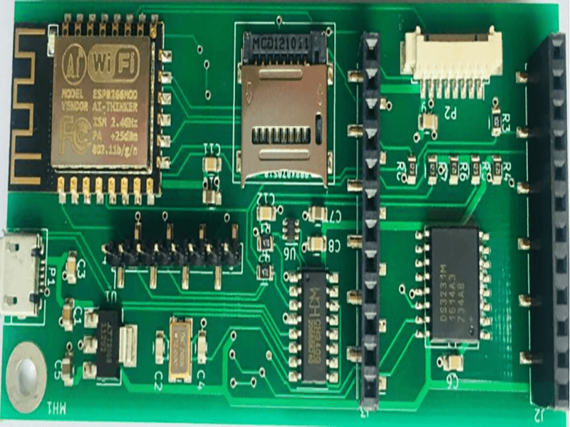
Where the Error Comes From
Registration error accumulates through the whole mask process. The laminate shrinks and moves during lamination and baking, the artwork or the direct imaging unit has its own alignment error, exposure and development introduce further variation, and the drill position adds a different reference. On a thick multilayer board the accumulated movement can be several times the error seen on a simple two layer panel.
Material behaviour is often the largest single contributor. Different resin systems, different glass styles and different copper balances shrink by different amounts, and a panel with heavy copper on one side and little on the other will move asymmetrically. That is why copper balance and symmetric stackups are practical assembly issues and not just cosmetic preferences.
Mask Expansion and Design Allowance
Mask expansion is the amount by which each opening is grown beyond the pad, and it exists precisely to absorb registration error. Too little expansion and the mask encroaches on the pad; too much and the dam between adjacent openings disappears. The correct value is a balance between the two, and it depends on the registration tolerance of the shop that will build the board.
The allowance should be written into the design rules together with the pad geometry. A designer who copies an expansion value from another product with a different layer count, a different laminate and a different supplier is guessing. On fine pitch work the value has to be confirmed with the fabricator, because the window between encroachment and dam loss can be only a few tens of micrometres wide.

Consequences on the Pad
When the opening shifts, the effective pad becomes smaller and asymmetric. Solder paste release from the stencil changes because the gasketing area changes, and the resulting joint is short of material on one side. On a small passive that imbalance is enough to rotate the part during reflow or to produce a weak fillet that passes visual inspection and fails in the field.
Covered copper is the other failure mode. Mask over the edge of a pad reduces the area available for wetting and can trap flux residues that later cause electrochemical migration. On a test point or a press fit hole the same encroachment can prevent the probe or the pin from making contact at all, which is why registration matters on features that are never soldered.
Slivers, Skips and Assembly Defects
A mask sliver is a very thin strip of coating left between two openings, normally one that the artwork did not intend to create. It is fragile, it does not adhere well over a sharp copper edge, and it tends to break off during handling or cleaning. Once loose, it becomes a particle that can land on a pad and produce a void, a bridging defect or a lifted component.
Skips are the opposite problem: coating missing where it should be, leaving bare copper in an area that is neither a pad nor a test point. Both defects are controlled by deleting features narrower than the process limit and by checking the mask layer with the same rigour as the copper layer. Our notes on solder mask and paste mask describe where each layer is defined.
Measuring and Specifying Registration
Registration is measured against targets placed on the production panel, and the result is normally quoted as a maximum displacement in each direction rather than as a single number. The measurement should be taken after the mask is fully cured, because the coating continues to move slightly as it sets, and it should be reported at several points across the panel rather than at the centre alone.
For a dense product it is worth specifying the registration tolerance explicitly and asking for the measurement to be recorded on the first article report. The figures in PCB manufacturing tolerances give a realistic starting point, and they should be read together with the copper registration figure rather than in isolation.
Designing for a Wider Window
The most effective fix is generous pad geometry. A pad with a little extra copper on each side tolerates a larger registration error before the joint is affected, and it costs nothing except a slightly wider opening. Designing to the smallest possible pad removes that margin in exchange for board area that is usually available anyway.
Beyond pad size, keep the stackup symmetric, balance the copper, avoid unnecessary thin mask features and confirm the expansion rule with the supplier before release. Our notes on PCB design quality characteristics and PCB yield and quality control set out the checks that catch most registration problems before they reach production.
Inspection and Acceptance Criteria
Registration is judged at incoming inspection against written criteria rather than against a feeling that the board looks acceptable. The usual checks are the smallest remaining pad exposure on the tightest footprint, the narrowest dam that survived, and whether any copper is visible outside a defined opening. A single measurement on a convenient pad says very little, because the error varies across the panel.
The criteria should also describe what happens when a limit is missed. Cosmetic pad exposure on a large passive may be acceptable where the joint still forms, while the same exposure on a fine pitch lead or a press fit hole may be grounds for rejection. Writing that distinction down, with a coupon that travels with the panel, keeps the decision consistent from one lot to the next.
FAQ
What causes solder mask misregistration? Material shrinkage during lamination and baking, artwork or imaging alignment error, exposure and development variation, and drill position all contribute. On multilayer boards the accumulated movement is larger than on simple panels.
How much mask expansion should be used? Enough to cover the registration tolerance of the fabricator without eliminating the dam between adjacent openings. The value should be confirmed with the supplier for the specific stackup and layer count.
What happens if a mask sliver breaks off? It becomes a loose particle that can sit on a pad and cause a void, a bridge or a lifted component during reflow, which is why very narrow mask features are usually deleted by the fabricator rather than held.